Blastrac 2-45DTM, Operating Instructions Manual
Introducing the Blastrac 2-45DTM - an exceptional surface preparation machine with unmatched efficiency. Discover how to operate this state-of-the-art equipment effortlessly by downloading the comprehensive Operating Instructions Manual, available for free download at manualshive.com. Get the most out of your Blastrac 2-45DTM with this user-friendly manual.
Share
Download


Reviews:
No comments
Related manuals for 2-45DTM

Astro
Brand: Necta Pages: 13

BC100
Brand: UnionSpecial Pages: 32

DocuColor 5252
Brand: Xerox Pages: 22

PBS 2000
Brand: Rollabind Pages: 2

SircleBind CC-320
Brand: Sirclecorp Pages: 6

Quantum Stylist Touch
Brand: Singer Pages: 4

81500A
Brand: UnionSpecial Pages: 68

HZL-E71
Brand: JUKI Pages: 24

NC81200 CLASSES
Brand: Carpet Sergers Pages: 30
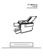
TF MEGA-A
Brand: Hefter Pages: 71

Thermal Binding Machine 8.2
Brand: Peleman Pages: 2

1200D
Brand: Janome Pages: 91

206M
Brand: MBM Pages: 19

275
Brand: Duerkopp Adler Pages: 36

VOCE Media
Brand: Crane Merchandising Systems Pages: 46

Frozen Gourmet
Brand: Crane Pages: 44

Dixie-Narco 504 P Series
Brand: Crane Pages: 99

1360
Brand: Beisler Pages: 71


