background image

USER MANUAL

NI cRIO-9032

Embedded CompactRIO Controller with Real-Time Processor and
Reconfigurable FPGA

This document describes the features of the National Instruments cRIO-9032 and contains
information about mounting and operating the device.
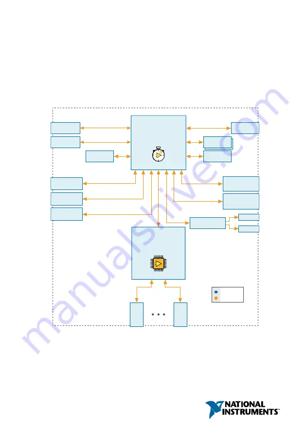
USB 2.0

Host Port

USB 2.0

Device Port

8 GB SATA

Disk-On-Chip

RJ-50

RS-232

Serial Port

RJ-50

RS-485/422 (DTE)

Serial Port

Intel Atom

E3825 1.33 GHz Dual-Core

System-On-Chip

+

+

Xilinx

Kintex-7 FPGA

7K160T

+

+

RJ-45 Gigabit

Ethernet Port 1

RJ-45 Gigabit

Ethernet Port 2

2 GB DDR3L

cRIO-9032

Hardware
Data

C Series

Module

C Series

Module

Mini

DisplayPort

USB 2.0

Host Port

Antenna

Antenna

2.4 / 5 GHz

WLAN Radio

Watchdog

Summary of Contents for cRIO-9032

Page 1: ...operating the device USB 2 0 Host Port USB 2 0 Device Port 8 GB SATA Disk On Chip RJ 50 RS 232 Serial Port RJ 50 RS 485 422 DTE Serial Port Intel Atom E3825 1 33 GHz Dual Core System On Chip Xilinx Kintex 7 FPGA 7K160T RJ 45 Gigabit Ethernet Port 1 RJ 45 Gigabit Ethernet Port 2 2 GB DDR3L cRIO 9032 Hardware Data C Series Module C Series Module Mini DisplayPort USB 2 0 Host Port Antenna Antenna 2 4...

Page 2: ...Alternate Mounting Configurations 32 BIOS Configuration 35 Resetting the System CMOS and BIOS Settings 35 Power On Self Test Warning Messages 36 BIOS Setup Utility 36 Main Setup Menu 37 Advanced Setup Menu 38 Boot Setup Menu 39 Save Exit Menu 41 Regional Regulatory Support for the cRIO 9032 42 Worldwide Support and Services 42 Configuring the cRIO 9032 You can connect the cRIO 9032 to a host compu...

Page 3: ...ss Adapter wlan0 section displays the search status 9 Click the System Settings tab and verify that the chassis has a wireless IP address along with the Ethernet IP address if the System State reads Connected Running the cRIO 9032 is connected to the wireless network Creating a Wireless Network with the cRIO 9032 Complete the following steps to connect the cRIO 9032 to a wireless network 1 Launch ...

Page 4: ...laptop 2 Ensure that any anti virus and firewall software running on the host computer allows connections to the host computer Note MAX uses UDP 44525 Refer to the documentation of your firewall software for information about configuring the firewall to allow communication through the UDP 44525 3 Launch MAX on the host computer 4 Expand Remote Systems in the configuration tree and locate your syst...

Page 5: ...ess control e Enter values for IPv4 Address Subnet Mask Gateway and DNS Server based on the information you recorded Be sure to enter a value for IPv4 Address that is not used by another device on the network For example do not use the IP address usually assigned to the host computer f Click Save and let MAX restart the cRIO 9032 The cRIO 9032 disappears from under Remote Systems and does not reap...

Page 6: ...his setting on prevents any LabVIEW startup applications from running Disable FPGA Startup App Rebooting the cRIO 9032 with this setting on prevents autoloading of any FPGA application Enable Secure Shell SSH Logins Rebooting the cRIO 9032 with this setting on starts sshd on the cRIO 9032 Starting sshd enables logins over SSH an encrypted communication protocol Note Visit ni com info and enter the...

Page 7: ... Antenna Port 1 5 RS 232 Serial Port 6 RS 485 422 DTE Serial Port 7 Mini DisplayPort 8 USB Host Ports 9 USB Device Port RJ 45 Gigabit Ethernet Ports The cRIO 9032 has two tri speed RJ 45 Gigabit Ethernet ports By default both Ethernet ports are enabled and configured to obtain an IP address automatically The Ethernet ports can be configured in MAX The following table shows the pinout for the RJ 45...

Page 8: ...use a crossover cable to connect to a host computer The following NI Ethernet cables are available for the cRIO 9032 Table 3 RJ 45 Gigabit Ethernet Cables Cables Length Part Number CAT 5E Ethernet Cable shielded 2 m 151733 02 5 m 151733 05 10 m 151733 10 Related Information Ethernet LED Indicators on page 20 Power Connector The cRIO 9032 has a power connector to which you can connect a primary and...

Page 9: ...RIO 9032 operates from the V2 input The cRIO 9032 has reverse voltage protection The following NI power supplies and accessories are available for the cRIO 9032 Table 5 Power Accessories Accessory Part Number NI PS 15 Power Supply 24 VDC 5 A 100 120 200 240 VAC Input 781093 01 NI PS 10 Desktop Power Supply 24 VDC 5 A 100 120 200 240 VAC Input 782698 01 4 Position Gold Power Supply Plugs Quantity 5...

Page 10: ...rom a low power state You can drive RI with a logic level high to wake the cRIO 9032 Refer to the specifications on ni com manuals for the RI wake voltage The following accessories are available to connect the RS 232 serial port to a 9 pin DSUB plug Table 7 RS 232 Serial Port Accessories Accessory Length Part Number RS 232 S8 Serial Cable 10 Position Modular Plug to 9 Pin DSUB 1 m 182845 01 2 m 18...

Page 11: ...e an isolated cable with the RS 485 422 DTE serial port The following accessory meets this requirement Table 9 RS 485 422 DTE Serial Port Accessory Accessory Length Part Number RS 485 S8 Serial Cable 10 Position Modular Plug to 9 Pin DSUB Isolated 1 m 184428 01 Mini DisplayPort Use the Mini DisplayPort to connect a monitor and implement a local HMI You can use a single real time VI to interactivel...

Page 12: ...ort Accessories Accessory Length Part Number Mini DisplayPort to Full DisplayPort Native Cable 0 5 m 157232 0R5 1 m 157232 01 2 m 157232 02 Mini DisplayPort to VGA Adapter Cable 0 5 m 157230 0R5 Mini DisplayPort to DVI Adapter Cable 0 5 m 157231 0R5 Mini DisplayPort Retention Accessory 156866 01 USB Host Ports The USB host ports on the cRIO 9032 support common USB mass storage devices such as USB ...

Page 13: ... 152166 02 Related Information File System on page 22 Installing a Ferrite on the USB Cables You must install a ferrite around all USB cables connected to the USB host ports to ensure that the cRIO 9032 meets all EMC standards applicable to your country What to Use Ferrite 711849 01 included with the cRIO 9032 USB cables What to Do Install the ferrite on the USB cables as shown in the following fi...

Page 14: ...devices while the cRIO 9032 is in a hazardous location or connected to high voltages If the cRIO 9032 is not in a hazardous location you can connect and disconnect USB devices without affecting operation The following table shows the pinout for the USB device port Description Signal Pin Pinout Pin Signal Description USB data D 3 1 4 2 3 2 D USB data Ground GND 4 1 VCC Cable power 5 V The following...

Page 15: ...mal wireless performance and reliability Caution In regions governed by the FCC and ETSI only those antennas tested with the device or similar antennas with equal or lesser gain may be used with this transmitter Depending on the regulatory region or country alternate antennas may not be covered by National Instruments transmitter certifications of the cRIO 9032 NI recommends using only antennas pr...

Page 16: ... on page 38 RESET Button Press the RESET button to reset the processor in the same manner as cycling power Troubleshooting Network Connectivity You can use the RESET button to troubleshoot network connectivity Complete the following steps to reset the network adapters to default settings 1 Hold the RESET button for 5 seconds and then release it to boot the controller in safe mode and enable Consol...

Page 17: ...bled Network settings reset RT Startup App disabled FPGA Startup App disabled Console Out enabled RT Startup App disabled FPGA Startup App disabled Safe Mode CMOS Reset Button The cRIO 9032 has a CMOS reset button that you can use to reset the CMOS and the BIOS LEDs The cRIO 9032 provides the following LEDs Figure 6 cRIO 9032 LEDs 5 4 1 2 3 6 1 POWER LED 2 STATUS LED 3 USER1 LED 4 USER FPGA1 LED 5...

Page 18: ...cators LED Color LED Pattern Indication Green Solid The cRIO 9032 is powered from the V1 input Yellow Solid The cRIO 9032 is powered from the V2 input Off The cRIO 9032 is powered off STATUS LED Indicators The following table describes the STATUS LED indicators 18 ni com NI cRIO 9032 User Manual ...

Page 19: ...easurement Automation Explorer MAX Help for information about safe mode Blinks four times and pauses The cRIO 9032 is in safe mode The software has crashed twice without rebooting or cycling power between crashes Continuously blinks The cRIO 9032 has not booted into NI Linux Real Time The cRIO 9032 either booted into an unsupported operating system was interrupted during the boot process or detect...

Page 20: ... Ethernet LED Indicators LED LED Color LED Pattern Indication ACT LINK Off LAN link not established Green Solid LAN link established Flashing Activity on LAN 10 100 1000 Yellow Solid 1 000 Mbit s data rate selected Green Solid 100 Mbit s data rate selected Off 10 Mbit s data rate selected WLAN Status LED Indicators The following table describes the WLAN Status LED indicators Table 21 WLAN Status L...

Page 21: ...connections visit ni com info and enter the Info Code emcground Internal Real Time Clock The cRIO 9032 contains an internal real time clock that maintains system time when the cRIO 9032 is powered off The system clock of the cRIO 9032 is synchronized with the internal real time clock at startup You can set the real time clock using the BIOS setup utility or MAX or you can set the clock programmati...

Page 22: ...yle C home directory This path is bound to the UNIX style directory home lvuser Various LabVIEW Real Time system files which would be accessible from C or C on other LabVIEW Real Time targets are found in different locations on this target UNIX style file systems support the concept of a symbolic link which allows access to a file using an alternative file path For example it is possible to link C...

Page 23: ...e cRIO 9032 using the Torx T10 driver 3 Slide the bracket into place aligning the three clearance screw holes 4 Install the M4 x 0 7 button head screw in the right end of the cRIO 9032 using the appropriate Torx T20 driver Tighten the screw to a maximum torque of 1 3 N m 11 5 lb in 1 The Module Immobilization accessory kit includes two sets of screws One set is a standard set of screws that requir...

Page 24: ...y dimensions for the cRIO 9032 Figure 8 cRIO 9032 Module Immobilization Accessory Dimensions 94 2 mm 3 71 in 1 6 mm 0 06 in 1 6 mm 0 06 in 220 4 mm 8 68 in Mounting the cRIO 9032 To obtain the maximum ambient temperature of 55 C you must mount the cRIO 9032 in the reference mounting configuration shown in the following image Mounting the cRIO 9032 in the reference mounting configuration ensures th...

Page 25: ...a metallic surface that is at least 1 6 mm 0 062 in thick and extends a minimum of 101 6 mm 4 in beyond all edges of the device Use the NI Panel Mounting Kit to mount the cRIO 9032 to a metallic surface that is at least 1 6 mm 0 062 in thick and extends a minimum of 101 6 mm 4 in beyond all edges of the device NI cRIO 9032 User Manual National Instruments 25 ...

Page 26: ...tion must meet the following requirements for cooling and cabling clearance Allow 25 4 mm 1 00 in on all sides of the cRIO 9032 for air circulation as shown in the following figure Figure 10 cRIO 9032 Cooling Dimensions 25 4 mm 1 00 in All Around Cooling Dimensions Allow the appropriate space in front of C Series modules for cabling clearance as shown in the following figure The different connecto...

Page 27: ...owing figure Figure 12 cRIO 9032 Ambient Temperature Location 63 5 mm 2 50 in 63 5 mm 2 50 in 1 1 1 38 1 mm 1 50 in 38 1 mm 1 50 in 63 5 mm 2 50 in 63 5 mm 2 50 in 1 1 Measure the ambient temperature here Dimensions The following figures show the front and side dimensions of the cRIO 9032 For detailed dimensional drawings and 3D models visit ni com dimensions and search for the module number NI cR...

Page 28: ...7 0 mm 4 21 in 219 5 mm 8 64 in 117 2 mm 4 61 in 8 6 mm 0 34 in 88 1 mm 3 47 in Figure 14 cRIO 9032 Antenna Dimensions 109 18 mm 4 30 in 113 75 mm 4 48 in 77 77 mm 3 06 in 222 2 mm 8 748 in Antenna Keepout 28 ni com NI cRIO 9032 User Manual ...

Page 29: ...ace For environments with high shock and vibration NI recommends mounting the cRIO 9032 directly on a flat rigid surface using the mounting holes in the cRIO 9032 What to Use cRIO 9032 M4 screw x4 user provided which must not exceed 8 mm of insertion into the cRIO 9032 What to Do Complete the following steps to mount the cRIO 9032 directly on a flat surface NI cRIO 9032 User Manual National Instru...

Page 30: ...ot exceed 8 mm of insertion into the cRIO 9032 Tighten the screws to a maximum torque of 1 3 N m 11 5 lb in Surface Mounting Dimensions The following figure shows the surface mounting dimensions for the cRIO 9032 Figure 16 cRIO 9032 Surface Mounting Dimensions 2 23 7 mm 0 94 in 2 20 3 mm 0 80 in 2 20 3 mm 0 80 in 6 ISO M4 0 7 Thread 8 mm Maximum Insertion Depth 116 5 mm 4 59 in 29 0 mm 1 14 in 30 ...

Page 31: ...g the screwdriver and M4 x 10 screws NI provides these screws with the panel mounting kit Tighten the screws to a maximum torque of 1 3 N m 11 5 lb in Note You must use the screws provided with the NI panel mounting kit because they are the correct depth and thread for the panel mounting plate 3 Fasten the panel mounting plate to the surface using the screwdriver and screws that are appropriate fo...

Page 32: ...g configurations The published accuracy specifications although not guaranteed for alternate mounting configurations may be met depending on the system power and the thermal performance of the alternate mounting configuration Contact NI for further details regarding the impact of common alternate mounting configurations on maximum operating temperature and module accuracy Mounting the Device on a ...

Page 33: ... rail mounting kit because they are the correct depth and thread for the DIN rail clip Clipping the Device on a DIN Rail Complete the following steps to clip the cRIO 9032 on a DIN rail 1 2 1 Insert one edge of the DIN rail into the deeper opening of the DIN rail clip 2 Press down firmly to compress the spring until the clip locks in place on the DIN rail Caution Ensure that no C Series modules ar...

Page 34: ... a rack mounting kit Mounting the Device on a Desktop You can use the NI desktop mounting kit to mount the cRIO 9032 on a desktop What to Use cRIO 9032 Screwdriver Phillips 2 NI desktop mounting kit 779473 01 Desktop mounting brackets x2 What to Do Complete the following steps to mount the cRIO 9032 on a desktop 1 2 1 2 1 Align the brackets with the mounting holes on the ends of the cRIO 9032 2 Us...

Page 35: ...nfiguration Resetting the System CMOS and BIOS Settings The cRIO 9032 BIOS configuration information is stored in a nonvolatile memory location that does not require a battery to preserve the settings Additionally the BIOS optimizes boot time by saving specific system information to memory backed up by a battery CMOS Complete the following steps to reset the CMOS and reset the BIOS settings to fac...

Page 36: ...o change configuration settings and to enable special functions The cRIO 9032 ships with configuration settings that work for most applications but you can use the BIOS setup utility to change configuration settings to meet the needs of your application Changing BIOS settings can cause incorrect behavior including failure to boot In general do not change a setting unless you are sure what the sett...

Page 37: ...information BIOS Version and Build Date These values indicate the version of the controller BIOS and the date on which the BIOS was built Embedded Firmware Version This value identifies the built in hardware capabilities Processor Type Base Processor Frequency and Active Processor Cores These values indicate the type of processor used in the controller the speed of the processor and the number of ...

Page 38: ...o Stay Off the cRIO 9032 returns to the soft off power state after AC power is restored When set to Turn On the cRIO 9032 powers on when DC power is restored Power Button Off Behavior This setting specifies how the system responds to the power button Valid options are Normal and Disabled The default value is Normal If the value is Normal the system responds to the power button as defined by the OS...

Page 39: ...descriptor Device Power Up Delay in Seconds This setting specifies the number of seconds the POST waits for a USB device or hub to power on This setting is only visible when the Device Power Up Delay is set to Manual The default value is 5 seconds Emulation Type This setting specifies how the BIOS presents the USB mass storage device to the system for each detected USB mass storage device This opt...

Page 40: ...e configurations to boot settings The factory default settings provide the most compatible and optimal configuration Setup Prompt Timeout This setting specifies the number of seconds the system waits for a BIOS Setup menu keypress the Delete key The default value is 2 seconds Bootup NumLock State This setting specifies the power on state of the keyboard NumLock setting The default value is On Hard...

Page 41: ...lect this option Save Changes Changes made to BIOS settings during this session are committed to NVRAM The setup utility remains active allowing further changes Discard Changes Any changes made to BIOS settings during this session of the BIOS setup utility are discarded The BIOS setup continues to be active Restore Factory Defaults This option restores all BIOS settings to the factory default This...

Page 42: ...866 ASK MYNI 275 6964 For support outside the United States visit the Worldwide Offices section of ni com niglobal to access the branch office websites which provide up to date contact information Information is subject to change without notice Refer to the NI Trademarks and Logo Guidelines at ni com trademarks for information on NI trademarks Other product and company names mentioned herein are t...

Reviews: