Motorola STARLINE SLE Series, Installation And Operation Manual
The Motorola STARLINE SLE Series offers cutting-edge technology for seamless communication. Ensure a flawless installation and operation with our comprehensive Installation And Operation Manual. Download this manual for free from our website manualshive.com, enabling you to optimize the performance of your STARLINE SLE Series effortlessly.
Share
Download


Reviews:
No comments
Related manuals for STARLINE SLE Series

KSB655
Brand: Kambrook Pages: 20
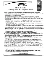
Blender
Brand: F'real Pages: 2

Versa BLSTVB-103
Brand: Oster Pages: 21

Xtendex ST-C5KVM-300
Brand: NTI Pages: 16

IP Solutions VIP-800
Brand: Valcom Pages: 4

RE750
Brand: Cudy Pages: 2

7745
Brand: OBH Nordica Pages: 68

Digital Xtreme Series
Brand: Aurora Pages: 15

SecureMesh XTEN-1000
Brand: Trilliant Pages: 21

POE-E101
Brand: Planet Pages: 2

230602
Brand: Hendi Pages: 100

Space-Saving Blender
Brand: Hamilton Beach Pages: 24

FO-DVI-1080LC-Set
Brand: Avenview Pages: 10

Voyager USB
Brand: Tvone Pages: 2

Kitchen Wizard DKM9801-DC
Brand: Dome Pages: 20

Explore 7
Brand: Electrolux Pages: 36

EMB3005
Brand: Electrolux Pages: 32

EBR9804S
Brand: Electrolux Pages: 40


