background image

CR5905 Hand Crimp Tool 

Doc No.  11-01-0195 

Release Date: 04-13-93 

UNCONTROLLED COPY


Page 1 of 4 

Revision: C 

Revision Date: 07-28-04 
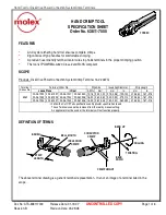
INSULATION 

CRIMP 

BRUSH 

STRIP 

LENGTH 

BELL MOUTH 

CRIMP HEIGHT 

BEND 

DOWN 

BEND UP 

ROLLING 

CONDUCTOR 

CRIMP 

TWISTING 


HAND CRIMP TOOL


Operating Instruction and 

Specification Sheet 

Order No. 11-01-0195 (CR5905)


FEATURES 

Œ 

Small handle spread which make this style tool ideally suited for end users 

Œ 

Ratchet with safety release that ensures consistent performance 

Œ 

A precision user-friendly terminal locator wire stop holds terminals in the proper crimping position 


SCOPE 

Wire Size 

Insulation Diameter 

Strip Length 

Terminal 

Series No. 

AWG 

mm² mm In. mm In. 

5230  22 

30 0.35-0.05 1.10-1.50 .043-.060 2.54-3.17 .100-.125 


DEFINITION OF TERMS 


The above terminal drawing is a generic terminal representation.  It is not an image of a terminal listed in the scope. 


CONDITIONS: 

 
After crimping, the conductor profiles should measure the following (see notes on page 3). 


Punch Width (Ref) 

Wire Size 

Cond. Crimp 

Height (Ref) 

Cond. Ins. 

Pull Force Min.  Profile 

Terminal 

Series No. 

AWG mm

2

  mm 

In.  mm In. mm In.  N  Lb. A B 

5230 

22  0.35 0.80-0.90 .031-.035 1.22 .048 1.30 .051  44.5  10.00 X   

5230 

24  0.20 0.78-0.88 .031-.035 1.22 .048 1.30 .051  28.9  6.50 X   

5230 

26  0.12 0.71-0.81 .028-.032 1.22 .048 1.30 .051  17.8  4.00    X 

5230 

28  0.08 0.69-0.79 .027-.031 1.22 .048 1.30 .051  11.1  2.50    X 

5230 

30  0.05 0.68-0.78 .027-.031 1.22 .048 1.30 .051  6.7  1.50    X 


Summary of Contents for CR5905

Page 1: ...ulation Diameter Strip Length Terminal Series No AWG mm mm In mm In 5230 22 30 0 35 0 05 1 10 1 50 043 060 2 54 3 17 100 125 DEFINITION OF TERMS The above terminal drawing is a generic terminal representation It is not an image of a terminal listed in the scope CONDITIONS After crimping the conductor profiles should measure the following see notes on page 3 Punch Width Ref Wire Size Cond Crimp Hei...

Page 2: ...ntil the ratchet releases See Figure 4 5 Lift the locator blade or wire stop up 6 Carefully remove the crimped terminal Maintenance It is recommended that each operator of the tool be made aware of and responsible for the following maintenance steps 1 Remove dust moisture and other contaminants with a clean brush or soft lint free cloth 2 Do not use any abrasive materials that could damage the too...

Page 3: ...ree of charge This will not be applicable to altered misused or damaged tools This tool is designed for hand use only Any clamping fixturing or use of handle extensions voids this warranty Hand held crimping tools are intended for low volume prototyping or repair requirements only Notes 1 This tool should only be used for the terminals and wire gauges specified on this sheet 2 This tool is not adj...

Page 4: ...y 1 11 11 0335 Locator Assembly 1 2 11 11 0324 Spring Main 1 3 11 11 0320 Spring Ratchet 1 Not all tools are equipped with a locator or locator blade Molex Application Tooling Group 1150 E Diehl Road Naperville IL 60563 Tel 630 969 4550 Fax 630 505 0049 Visit our Web site at http www molex com M4 NUT RATCHET RELEASE LEVER ADJUSTMENT RING LOCATOR BLADE 2 Figure 4 1 M4 X 18LG BHCS 3 ...

Reviews: