Mikasa MVH-100, Service Manual
The Mikasa MVH-100 is a top-of-the-line compactor that delivers superior performance and durability. Ensure your equipment is properly maintained with the free Service Manual available for download from manualshive.com. This comprehensive manual provides detailed instructions for servicing and maintaining your MVH-100, maximizing its lifespan and efficiency.
Share
Download


Reviews:
No comments
Related manuals for MVH-100

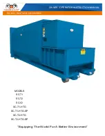
FB-42RY
Brand: Brinly Pages: 60
SC-02
Brand: CRAM-A-LOT Pages: 42

Monogram Compactor
Brand: GE Pages: 12

Monogram GCG1000
Brand: GE Pages: 12

MONOGRAM ZCG3100 BB
Brand: GE Pages: 16
GCG1520
Brand: GE Pages: 20
GCG1500P
Brand: GE Pages: 28
GCG1200
Brand: GE Pages: 16
GCG1700LII
Brand: GE Pages: 2

33 27JD Series
Brand: MTD Pages: 80

2122.6
Brand: Belarus Pages: 248

Jivo 245 DI
Brand: Mahindra Pages: 87

273 4WD
Brand: Captain Pages: 121

Cropmaster VAK1 Series
Brand: David Brown Pages: 51

UpFront STS 16
Brand: Hagie Pages: 127

Belarus 90
Brand: MTW Pages: 123

PELLE RETRO PR-1500-P
Brand: CHARGEUR Pages: 25

2690816
Brand: Briggs & Stratton Pages: 12


