


User’s Manual
Microedge Instruments Inc.
407 – 15216 North Bluff Road
White Rock, BC, Canada, V4B 0A7
Toll Free: 1.877.352.9158
www.microedgeinstruments.com
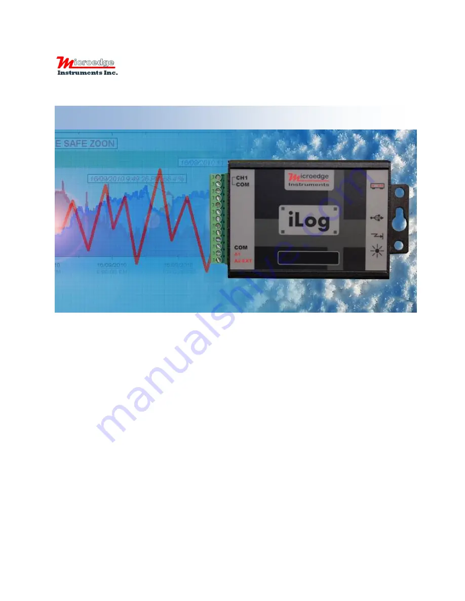
Compact Data Loggers
iLog Series
407 – 15216 North Bluff Road
White Rock, BC
Canada V4B 0A7
Phone: 604.424.9092
Toll Free: 1.877.352.9158
Fax: 1.877.453.0658
Email: [email protected]
Web: www.microedgeinstruments.com
Содержание iLog Series
Страница 31: ...iLog Data Loggers User s Manual Page 30 63 ...
Страница 34: ...iLog Data Loggers User s Manual Page 33 63 Click Next button to proceed to the next page ...
Страница 56: ...iLog Data Loggers User s Manual Page 55 63 Real Time in Horizontal View Real Time In Vertical View ...
Страница 61: ...iLog Data Loggers User s Manual Page 60 63 ...


