Maxtor DiamondMax Plus9 120GB AT, Product Manual
The Maxtor DiamondMax Plus9 120GB AT provides reliable storage for your data needs. Easily set up and utilize your device with the comprehensive Product Manual available for a hassle-free experience. Visit our website to download this FREE manual and get the most out of your Maxtor DiamondMax Plus9.
Share
Download


Reviews:
No comments
Related manuals for DiamondMax Plus9 120GB AT
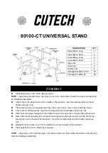
80100-CT
Brand: Cutech Pages: 2

DataTraveler Locker+ Generation 3 DTLPG3
Brand: Kingston Technology Pages: 1623

60066
Brand: Lifetime Pages: 32

ES424X6+BHP
Brand: Sans Digital Pages: 2

7000DLT Series
Brand: Quantum Pages: 312

Aeon J460 M2 JBOD
Brand: Netberg Pages: 67

9065890
Brand: P.Lindberg Pages: 22

Meridian
Brand: HermanMiller Pages: 5

ORSY Flex 350
Brand: Würth Pages: 196

DataDock 350
Brand: MicroNet Pages: 33
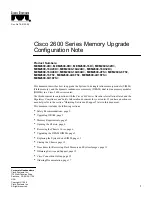
MEM2600-16D
Brand: Cisco Pages: 18

MDS 9509
Brand: Cisco Pages: 8
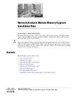
MEM-C6KNAM-2GB
Brand: Cisco Pages: 20

CSS8-IDM-MEM-HD
Brand: Cisco Pages: 4

NSS 300 Series
Brand: Cisco Pages: 2

Memory Card MEMCUE-256D=
Brand: Cisco Pages: 8

NSS 324
Brand: Cisco Pages: 36

NSS 300 Series
Brand: Cisco Pages: 265


