background image

02/20 Rev. B 57-02064 
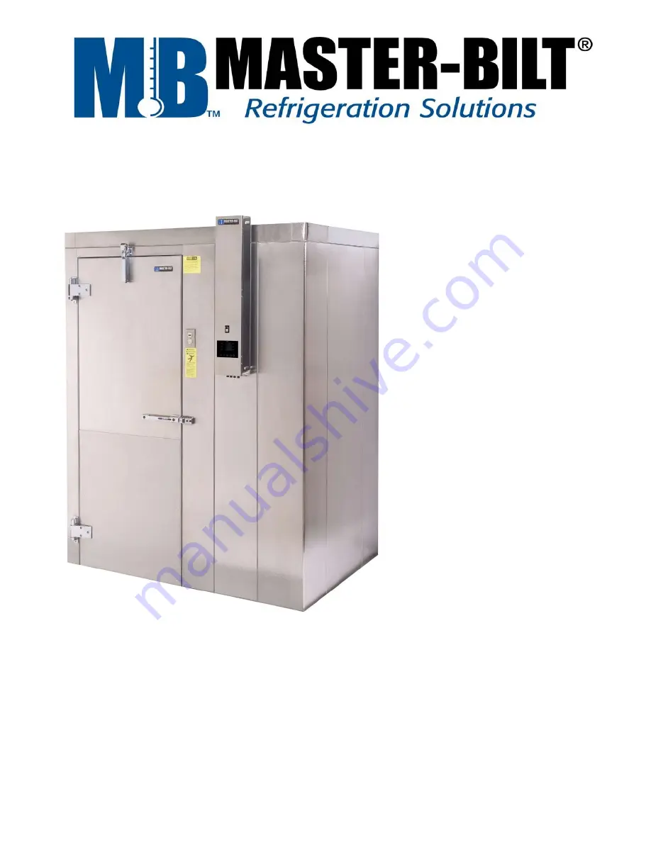


Blast Chiller 

Installation & Operation Instructions 


MCR/MCF – 33101 


MCR/MCF – 33102 


MCR/MCF – 33101PT 


MCR/MCF – 33102PT 


Master-Bilt Products 

908 Highway 15 North 

New Albany, MS 38652 

Phone: (800) 684-8988 


©2014 Master-Bilt Products, an unincorporated division of Standex International Corporation. All rights reserved. 

Printed in U.S.A. 

Summary of Contents for Master-Chill MCR-33-101PT

Page 1: ...ns MCR MCF 33101 MCR MCF 33102 MCR MCF 33101PT MCR MCF 33102PT Master Bilt Products 908 Highway 15 North New Albany MS 38652 Phone 800 684 8988 2014 Master Bilt Products an unincorporated division of Standex International Corporation All rights reserved Printed in U S A ...

Page 2: ...2 ...

Page 3: ...5 PREPARE FLOOR AND INSTALL FLOOR ANGLES 15 INSTALL INSULATED WALL PANELS 16 INSTALL EVAPORATOR AND FAN ASSEMBLIES 17 18 INSTALL CEILING PANELS 19 INSTALLATION OF DOOR PANEL 20 21 INSTALL INTERIOR TRIM 21 ROUTE TEMPERATURE SENSOR MOUNT CONTROL PANEL 22 CONTROL WIRING 23 24 INSTALL EXTERIOR TRIM 24 CHECK DRAIN FOR LEAKS 25 CHECK DOOR SWING 25 DELIVERY INSPECTION 26 INSTALLATION DATA 26 BLAST CHILLE...

Page 4: ...Master Bilt Blast Chiller are marred or destroyed contact Master Bilt to replace them Locate the serial number plate on the Blast Chiller Write the 10 digit serial number below Your Master Bilt dealer needs this number when you order parts Serial Number ________________________ COPYRIGHT 1994 BY STANDEX INTERNATIONAL CORPORATION NOTICE Read this manual carefully before you begin Blast Chiller inst...

Page 5: ...l Master Bilt Blast Chillers A customized print is provided specific to your order Your print provides information specific to your design and installation This manual indicates when you should refer to your site specific drawings BLAST CHILLER MODELS All Blast Chiller electrical connections should be made per the wiring diagrams found in this manual for the electrical box and control panel All Bl...

Page 6: ...ation is presented in this section and throughout the manual These signal words are used in the warnings and safety messages DANGER Severe injury or death will occur if you ignore the message WARNING Severe injury or death can occur if you ignore the message CAUTION Minor injury or damage to your Master Bilt Blast Chiller can occur if you ignore the message CAUTION also calls attention to safety m...

Page 7: ...unded Check ground connection Do not use if unit is not grounded PREPARE FOR EMERGENCIES Be prepared if a fire starts Keep a first aid kit and fire extinguisher handy Keep emergency numbers for doctors ambulance service hospital and fire department near your telephone WARNING TO EMPLOYERS Never allow small children inside or around your blast chiller They can become trapped inside and be injured o...

Page 8: ...tc and an electrical supply for the condensing unit ELECTRICAL CONNECTIONS The wiring must be performed by a qualified and certified electrician Improper or faulty hook up of electrical components of the walk in can result in severe injury or death Installation of the refrigeration and electrical components of the walk in must be performed only by a refrigeration mechanic or licensed electrician N...

Page 9: ...ions Manual Customized drawings and diagrams for your specific order Installation diagram Panel numbering diagram Wiring diagram 2 identical wiring diagrams are provided One is included in the envelope for use at the installation site One is a permanent part of your manual AFTER INSTALLATION Complete the Installation Data on pages 44 to 46 Retain one copy Return one copy to Master Bilt Leave one c...

Page 10: ...embly ______ Control Box ______ Top Trim Panels ______ Top Trim Panel Mounting Strips ______ Evaporator Coil Assembly ______ Evaporator Fan Assembly ______ Interior Top Trim Panels ______ Interior Side Trim Panels ______ Box of Hardware Screws Bolts Light Globe Cam Lock Hole Plug Buttons Locking Wrench Installation Manual ______ Blast Chiller Rack ______ Compressor Condenser Unit ...

Page 11: ...refully in the van Carefully check your packing list page 8 to be sure all parts are received If parts are missing or damaged Make a notation to that effect on the driver s Bill of Lading Notify the van company at once Since van shipped parts are not crated handle and store them carefully before you begin installation ...

Page 12: ...ealed damage claims can be filed You as the consignee must file freight claims with the delivering truck line If there is any question whatsoever regarding the condition of the equipment this question should be noted on the bill of lading which you sign as a delivery receipt All shortages must be noted on the bill of lading as the shipment is received If a bill of lading is signed as complete for ...

Page 13: ...oors stack them vertically on skids with spacers between the panels This protects the panel edges and provides proper ventilation This method of stacking permits drain off of moisture and guards against rust stains Panels should be covered with a waterproof covering to protect them from the weather Master Bilt recommends black polyethylene sheeting which keeps sunlight out and eliminates the green...

Page 14: ...rain will exit the Blast Chiller box 4 Ensure electrical supply is near the Blast Chiller a Review the enclosed Blast Chiller print to determine the best location for the customer supplied electrical disconnects for the two electrical supplies required i On an adjacent wall for blast chiller ii At condensing unit b Measure and locate where the electrical supply will be located c Review the enclose...

Page 15: ...and the wall to assure adequate space is allowed c Refer to the Blast Chiller print the standard Master Bilt panel is 4 thick Correct any of the above issues with the floor BEFORE proceeding with Blast Chiller installation Use the provided 1 1 2 x 1 1 2 floor angles to attach the bottom of all wall sections or screeds to the existing floor Attach the floor angles to the existing floor before the w...

Page 16: ...s the panel together snugly as shown above Continue to erect the sides and back of the chiller box 1 Ensure the panels are even at the top Check all remaining cam locks 1 Tighten or re tighten as needed Press the cam lock covers plug covers into the holes with your hands NOTICE Occasionally a cam fastener may not operate because the hex pin socket is broken or damaged during assembly If one cam on...

Page 17: ...for a 1 hole penetration b The location of the drain will determine whether you need to run the piping through the predrilled holes in the evaporator and fan assemblies c Double check the hole location before drilling 2 Drill a 1 hole for drain line a Evaporator assembly may have to be moved to allow access to drill 3 Move evaporator and fan assemblies back into place and check hole location using...

Page 18: ...n s a Use a non permanent thread sealer because drain lines must be capable of being removed for future servicing Seal the inside drainpipe hole with NSF approved silicone sealant Seal the remainder of drainpipe hole in blast chiller wall with foam insulation 1 This will stop any airflow around the pipe ...

Page 19: ...d location will depend on the blast chiller and condensing unit purchased see the Condensing Unit and Refrigeration Unit Installation section in this manual to determine the correct location and hole sizes 4 Drill holes required DANGER DO NOT LIFT PANEL AT THE OUTER EDGES NOTICE Master bilt recommends safety be your first priority at all times Use either a forklift or a properly designed panel lif...

Page 20: ...st the face of the door frame to ensure correct vertical alignment and latch the door frame to the ceiling panel while holding level in place 3 Retighten the cam fasteners on the adjoining ceiling and wall panels Attach the optional threshold plate if provided 1 Apply a bead of caulking around the perimeter of the door threshold 2 Set the threshold in the door opening to maintain the opening width...

Page 21: ... In this step you install the interior trim INSTALL INTERIOR TRIM Install snap on cover caps on the door panel cam locks Use a level to plumb the evaporator and fan bank Use the flange as a template to mark the screw hole placement with a marking pen to make sure the evaporator and fan banks are installed plumb Line drill through the holes in the flange using a 3 16 18 drill Insert size 1 4 x 3 4 ...

Page 22: ...nting holes Position the control panel so that the top conduit connection box is completely above the walk in top Secure the control panel to the walk in with 10 self tapping screws WARNING Beware of others on the opposite side of the panel when drilling through the wall CAUTION Do not drill holes through the evaporator or fan assemblies Cover wiring and controls to prevent drill shavings remainin...

Page 23: ... Drill hole through the ceiling above the fan tower assembly 3 Feed the flexible conduit labeled Fan through the ceiling as indicated in the graphic on the opposite page to the Blast Chiller Fan Assembly 4 Connect the wires 5 Assure the conduit watertight connection on the top of the fan bank is secure 6 Apply wire nut connectors included 7 Check fans and insure all blades turn freely 8 Replace th...

Page 24: ...ure the power voltage supply matches the Blast Chiller Data Plate STEP 9 In this step you install the exterior trim INSTALL EXTERIOR TRIM Locate the top trim channels and offset strips if provided Locate 8 32 hex head screws Locate the numbered trim channels and numbered offset strips Locate the pre formed corner fillers provided for each corner Determine the proper location on the Blast Chiller f...

Page 25: ...leaks Replace the evaporator coil and fan base cover panels STEP 11 In this step you check the door swing CHECK DOOR SWING Check the Blast Chiller door swing for proper opening and closing operation Observe the clearance from the door to the Blast Chiller door frame 1 Clearance should be even around the perimeter of the door 2 If even clearance is not observed adjust the door hinges ...

Page 26: ...TION DATA EQUIPMENT REQUIRED Pans and lids 1 Hold food during blast chill operation 2 Hold food for refrigerated storage Thermometer to check food temperature 0 200 F NOTICE Please read this section prior to installing your Blast Chiller Condensing Unit This information is based on good refrigeration practice and should be used as a guide for installation and operation of your equipment NOTICE To ...

Page 27: ...by for the start up of an operating cycle The run status the device is powered is on and an operating cycle is in progress Hereon the term device switch on means the passage from the stand by status to the on status The term switch off means passage from the on status to the stand by status If a power cut OFF occurs during the stand by status or during the on status the device will re propose the ...

Page 28: ... call ESCAPE key 5 cycle start cycle cut off key hereon called START STOP key 6 interactive keys 1 3 7 display 8 interactive keys 4 6 9 jumper for the insertion of the terminating resistor of the user interface control module communication port and of the RS 485 serial port 10 RS 485 serial port with MODBUS communication protocol and communication port with control module signal and power supply ...

Page 29: ...ese will be started again from the beginning If a timed controlled blast chilling or deep freezing operation was in progress these will be started again from the moment the power supply was cut off If storage was in progress this will be re proposed 1 Connect the device power supply the device will display the MASTER BILT splash screen for 10 seconds after which it will go to the stand by status 2...

Page 30: ...es the work set point during pre cooling When the cabinet temperature reaches that established with parameter r12 pre cooling continues and the buzzer is activated for 2 s Every operating cycle can be preceded by pre cooling SWITCHING ON UV LIGHT FOR STERILIZATION CYCLE Operate as follows 1 Make sure that parameter u11 is set at 2 2 Make sure the device is in the on status and that the door is clo...

Page 31: ...s 3 Press and release the key 1 press and release the key 2 and then press and release the START STOP key 3 The device will display the temperature detected by the needle probe and the cabinet temperature Output K6 is activated at maximum for the time established with parameter u8 or until the temperature detected by the needle probe reaches that established with parameter u7 closing the door if t...

Page 32: ...d 5 1 If the test is completed successfully the cycle will be started 5 2 If the test is not completed successfully the buzzer will be activated for 5 s every 60 s and the cycle will be started with timed control During blast chilling the device displays the temperature detected by the needle probe the cabinet temperature the program name if named and the time passed since the start of blast chill...

Page 33: ...ng duration count is started on condition that the temperature detected by the needle probe is below that established with program parameter r15 5 2 If the test is not completed successfully the buzzer will be activated for 5 s every 60 s and the cycle will be started with timed control During hard blast chilling phase the device displays the temperature detected by the needle probe the cabinet te...

Page 34: ...key to select the blast chilling duration and the work set point during blast chilling 4 1 Press and release the key or the key to modify these values and then the ESCAPE key to memorize them these values can also be memorized through parameters r1 and r7 5 Press and release the START STOP key the cycle will be started During blast chilling the device displays the residual blast chilling time the ...

Page 35: ...nd release the UP key or the DOWN key to select the blast chilling duration and the work set point during blast chilling 4 1 Press and release the key or the key to modify these values and then the ESCAPE key to memories them these values can also be memorized through parameters r1 and r7 5 Press and release the START STOP key 1 the cycle will be started During hard blast chilling the device displ...

Page 36: ... the MENU key and then press and release the UP key or the DOWN key to select the work setpoint during blast chilling 10 1 Press and release the key or the key to modify this value and then the ESCAPE key to memories it this value can also be memorized through parameters r1 and r7 11 Press and release the START STOP key 1 the cycle will be started During blast chilling the device displays the temp...

Page 37: ...mperature detected by the needle probe is below that established with parameter r15 5 2 If the test is not completed successfully the buzzer will be activated for 5s every 60s and the cycle will be started with timed control see A8 Time controlled deep freezing and storage During deep freezing the device displays the temperature detected by the needle probe the cabinet temperature the program name...

Page 38: ...se values and then the ESCAPE key to memories them these values can also be memorized through parameters r4 and r8 5 Press and release the START STOP key 1 the test to verify the correct insertion of the needle probe will be started Test for verification of the correct insertion of the needle probe 5 1 If the test is completed successfully the cycle will be started The maximum deep freezing durati...

Page 39: ...zer will be activated for the period of time established with parameter AA to indicate that the cycle has been completed If the temperature detected by the needle probe does not reach the deep freezing end temperature within the maximum deep freezing duration deep freezing will not be completed successfully but will continue and the buzzer will be activated Press and release a key to restore norma...

Page 40: ... duration and the work set point during deep freezing 4 1 Press and release the key or the key to modify these values and then the ESCAPE key to memories them these values can also be memorized through parameters r2 and r8 setpoint 5 Press and release the START STOP key 1 the cycle will be started During blast chilling the device displays the residual deep freezing time the temperature of the cabi...

Page 41: ... then the ESCAPE key to memories them these values can also be memorized through parameters r2 and r8 setpoints 5 Press and release the START STOP key 1 the cycle will be started During soft deep freezing phase the device displays the residual deep freezing time the temperature of the cabinet the name of the program if named and the time passed from the start of deep freezing 6 The cycle can be st...

Page 42: ... the MENU key and then press and release the UP key or the DOWN key to select the work setpoint during deep freezing 4 1 Press and release the key or the key to modify this value and then the ESCAPE key to memories it this value can also be memorized through parameter r8 setpoint 5 Press and release the START STOP key 1 the cycle will be started During deep freezing the device displays the tempera...

Page 43: ...the buzzer is activated for 2s to indicate that the pre cooling cycle has been completed SWITCHING ON UV LIGHT FOR STERILIZATION CYCLE if available Operate as follows 1 Make sure that parameter u11 is set at 2 2 Make sure the device is in the ON status and that the door is closed the door switch is not active 3 Make sure that the keyboard is not locked and that no procedure is in progress 4 Press ...

Page 44: ...th parameter u7 closing the door i e the deactivation of the door micro switch input causes heating to be cut off The buzzer is activated for 2s to indicate the needle heating process completed SAVE MEMORISATION OF A PROGRAM 1 Make sure that the keyboard is not locked and that no procedure is in progress 2 Press and release the key 1 before starting a operating cycle that desires The device will d...

Page 45: ...oller deep freezing temp see also r6 C F 99 99 18 0 r5 Max duration of Temperature controlled blast chilling see also r3 Min 1 500 90 90 r6 Max duration of Temperature controlled deep freezing see also r4 Min 1 500 240 240 r7 Box temperature set point for blast chilling soft deep freezing C F 99 99 0 32 r8 Box Temperature setpoint during deep freezing see also r0 C F 99 99 26 15 r9 Box Temperature...

Page 46: ...n off 2 Air fan on 3 air with door open fan on 0 3 2 0 2 0 d2 Defrost termination Temperature coil also see d3 C F 99 99 7 45 d3 Defrost Duration 0 defrost will never activate Min 0 99 30 30 d4 Defrost Start up of blast chilling and deep freezing cycle 1 yes 0 1 1 1 d5 Defrosting delay on start up Min 0 99 0 0 d7 Drip time duration Min 0 15 2 2 d15 Minimum duration of compressor switch on activati...

Page 47: ... 68 F17 Box temp above which evap fan is off during pre cooling both cycles C F 99 99 90 194 F18 Evaporator Fan Speed 1 0 100 20 20 F19 Evaporator Fan Speed 2 0 100 40 40 F20 Evaporator Fan Speed 3 0 100 60 60 F21 Evaporator Fan Speed 4 0 100 80 80 F22 Evaporator Fan Speed 5 0 100 100 100 F23 Evaporator fan speed on during blast chilling 1 20 5 100 1 2 3 4 5 5 5 F24 Evaporator fan speed on during ...

Page 48: ...rding interval during cycle Min 0 240 2 2 L2 Recording interval during store Min 0 240 5 5 LA Device address 1 247 247 247 Lb Baud rate 0 2 400 baud 1 4 800 baud 2 9 600 baud 3 19 200 baud 0 1 2 3 2 2 LP Parity 0 none 1 odd 2 even 0 1 2 3 2 2 Various Parameters PAR Description Unit Range ºC ºF E8 Keyboard lock function mode 0 disable 1 Manual with permanent effect 2 manual with temporary effect 0 ...

Page 49: ...ing operated as follows 3 1 Make sure the device is in the ON status 3 2 Make sure the keyboard is not Locked and no procedure is in progress 3 3 Press and release HOME key 1 press and release the MENU key 2 then press and release the key 3 to select HACCP ALARMS 3 4 Press and release the key 4 then press and release key 5 to select SETUP RECORDING 3 5 Press and lease the SET key press and release...

Page 50: ...e for blast chilling 1 Stainless steel or aluminum permanent ware a 12 x 20 x 2 1 2 pans b Also 18 x 26 or fractional size pans can be used with wire shelves Lids or covers of any kind are NOT used during blast chilling Cover foods AFTER blast chilling Label food pans 1 Include type of food and date of production see your Cook Chill Training Manual Stored under normal refrigeration conditions WARN...

Page 51: ...ire 12 15 minutes of blast chilling time High density foods such as stews or roasts may require up to 90 minutes of blast chilling time Pans of poached scrambled or fried eggs cool to 36 40 F more quickly than pans of beef stew Check food temperature with an accurate hand held thermometer LEAVE FOODS UNCOVERED DURING BLAST CHILLING Pans of food should not be covered during blast chilling 1 Covers ...

Page 52: ...he requirements against the following 1 Power supply 2 Amperage draw Set the temperature control for the desired temperature range 1 Locate the thermostat inside the control box see drawing on opposite page 2 Holding temperature should be 37 F 3 Blast Chilling temperature should be 35 F 4 Blast freezing temperature should be 10 F Check the superheat setting of the thermostatic expansion valve for ...

Page 53: ...omplete the following data Three copies are enclosed 1 Retain one copy for your records 2 Return one copy to Master bilt 908 Highway 15 North New Albany MS 38652 3 Leave one copy at the installation site Model ___________________________________ Company Organization _______________________________________________ Street Address _______________________________________________________ DANGER Avoid e...

Page 54: ...______________________________ Thermostat Setting Electrical Volts Phase Holding _____ F _____ F _____ F _____ F Chilling _____ F _____ F _____ F _____ F Operating Pressure Suction ____________psig Liquid __________psig INSTALLATION DATA Complete the following data Three copies are enclosed 1 Retain one copy for your records 2 Return one copy to Master bilt 908 Highway 15 North New Albany MS 38652...

Page 55: ...______________________________ Thermostat Setting Electrical Volts Phase Holding _____ F _____ F _____ F _____ F Chilling _____ F _____ F _____ F _____ F Operating Pressure Suction ____________psig Liquid __________psig INSTALLATION DATA Complete the following data Three copies are enclosed 1 Retain one copy for your records 2 Return one copy to Master bilt 908 Highway 15 North New Albany MS 38652...

Page 56: ..._ Phone _______________________________ Compressor Condensing Unit s Electrical _________________ Volts ____________ Phase _______________ Model s _____________________________________ Serial s ______________________________________ Thermostat Setting Electrical Volts Phase Holding _____ F _____ F _____ F _____ F Chilling _____ F _____ F _____ F _____ F Operating Pressure Suction ____________psig ...

Page 57: ...57 EVFTFT818 REMOVABLE PROBE ASSEMBLIES EVFTFT818 ...

Page 58: ...New Albany MS 38652 Service Dept phone 800 684 8988 Fax 866 882 7629 Email service master bilt com 2014 Master Bilt Products an unincorporated division of Standex International Corporation All rights reserved Printed in U S A ...

Reviews: