background image

STEAM-TECH 

PLUS 

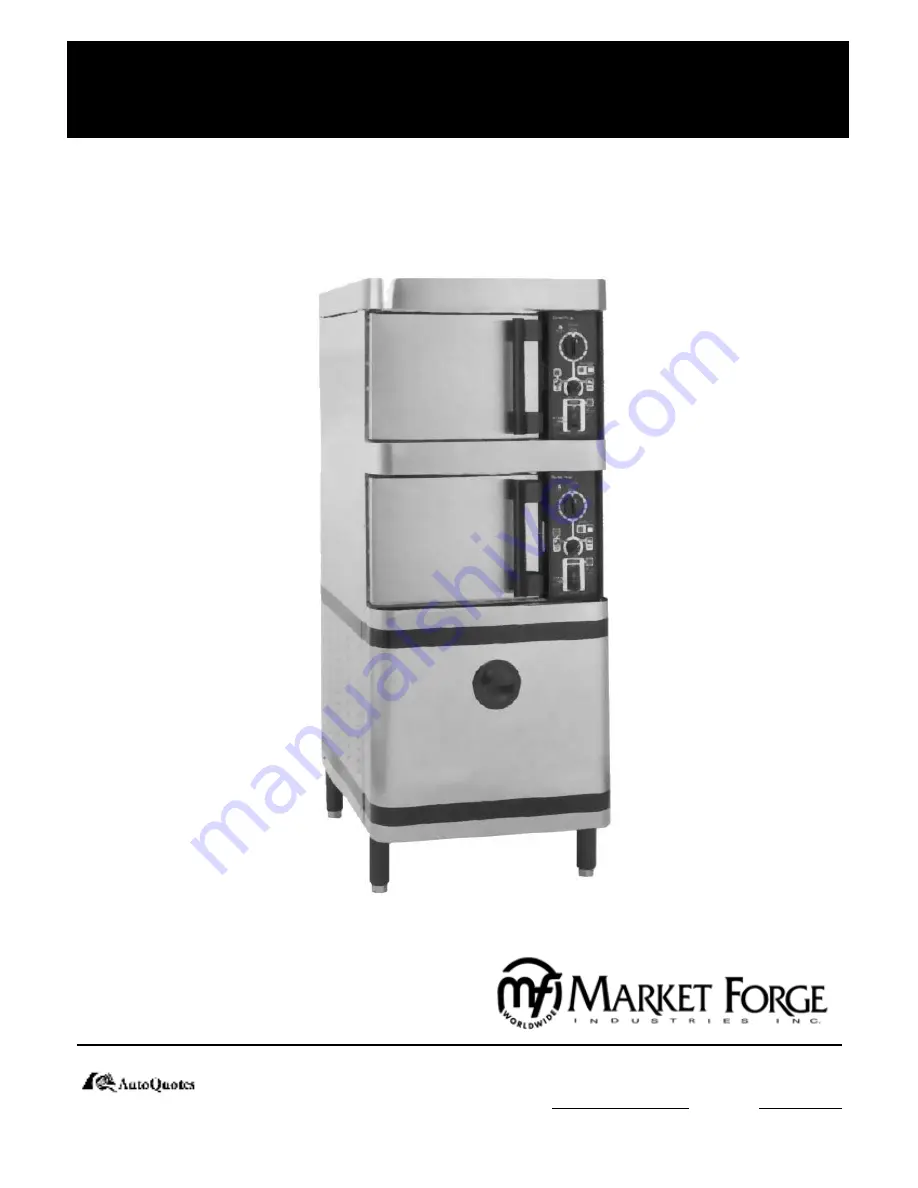
ELECTRIC STEAM COOKER

STP-6E

OWNER’S MANUAL

Printed in U.S.A.   

 35 Garvey Street 

l

 Everett 

l

 MA 

l

 02149

Tel: (617) 387-4100 

l

 Toll Free: (888) 698-3188 

Fax: (617) 387-4456 

l

 Outside MA Fax: (800) 227-2659

E-Mail: 

[email protected]


l

 Website: 

www.mfii.com

Form Number: S-2464          01/07

An Employee Owned Company

Summary of Contents for STEAM-TECH PLUS STP-6E

Page 1: ...S MANUAL Printed in U S A 35 Garvey Street l Everett l MA l 02149 Tel 617 387 4100 l Toll Free 888 698 3188 Fax 617 387 4456 l Outside MA Fax 800 227 2659 E Mail CUSTSERV mfii com l Website www mfii com Form Number S 2464 01 07 An Employee Owned Company ...

Page 2: ...l Control Board 5 3 6 MAINTENANCE 6 1 General 6 1 6 2 Daily Cleaning 6 1 6 3 Preventive Maintenance 6 1 6 4 Cleaning The Generator 6 1 6 4 1 Cleaning Instructions 6 1 Figure 6 1 Exterior Steal Metal Cover Panel Fasteners Parts List 6 2 6 5 Cleaning The Steam ventilation Ductwork 6 3 6 6 Electrical Box Service Access 6 3 Figure 6 2 Electrical Panel Assembly Parts List 6 4 Figure 6 3 Timer Settings ...

Page 3: ...vels have been reached the heating element is energized When the water temperature 1 2 3 4 5 in the steam generator has reached 193O F the green READY light is illuminated indicating that the unit is now ready to make steam and all controls are functional Set the MODE SELECT switch to either STEAM or STEAM HOLD After selecting a mode the TIMER knob must be set to the desired cooking time for the g...

Page 4: ... for future reference 2 2 SERVICE CONNECTIONS All service connections are made at the bottom of the unit in the 6 inch high space between the floor and the bottom of the cabinet Please see figure 2 1 and table 2 1 for service connec tions details and dimensions 2 2 1 WATER CONNECTIONS Before connecting the water to this unit have water supply analyzed to make sure that hardness is no greater than ...

Page 5: ...t of the unit Slide the door upwards off the bottom hinge Remove the two 5 16 bolts that attach the bottom hinge to 1 2 3 4 5 the front of the unit NOTE The top hinge is slightly larger than the bottom hinge Remove the 4 black plastic hole plugs from the front unit Push the black hole plugs into the now vacant left upper and lower hinge mounting holes Reinstall the top larger hinge and bolts into ...

Page 6: ...n while pushing the panel in towards the unit slide it down into position Replace screw Rotate the door 180O for mounting 11 12 13 Slide the remaining small hinge into the top door bear ing Slide the door and hinge assembly down onto the hinge which you have already mounted to the front of the unit Use the two 5 16 bolts to mount the top hinge into the right upper hinge mounting holes DO NOT COMPL...

Page 7: ...TEAM ON win dow located near the top of the control panel should light up green At the same time the STEAM DEMAND window should light up red After a short time the red STEAM DEMAND light will begin to cycle on and off while the green STEAM ON light stays on continuously When the timer reaches 0 minutes the buzzer will sound and both the STEAM ON and the STEAM DEMAND light will turn off The buzzer ...

Page 8: ...ill be heard as the cool air is evacuated from the cooking com partment and replaced with a fresh steam from the generator he unit will continue to cycle normally as it was before the door was opened NOTE Repeat steps in section 3 2 through section 3 7 for both the upper and lower cooking compartments to insure proper functioning of the entire unit before proceeding to the next sec tion shutdown 3...

Page 9: ...le malfunction and the need for maintenance Continued use of the equipment without maintenance will create a potential for scalding 1 2 3 4 5 6 7 8 4 2 3 SHUT DOWN No special procedure is necessary for shutting the unit down Simply press the POWER switch into the OFF position All indi cator lights on the control panel will go out and the generator for the cooking compartment will drain The temperi...

Page 10: ... INDICATOR LIGHT CONSTANT STEAM BUTTON STEAM INDICATOR READY INDICATOR LIGHT CLEAN GENERATOR POWER ON INDICATOR LIGHT POWER SWITCH MODE SELECTOR SWITCH PILOT LIGHT PILOT LIGHT STEAM HOLD INDICATOR HOLD INDICATOR FULLY FEATURED NOT FULLY FEATURED 4 2 4 OPERATION FIGURE 4 1 CONTROL PANEL ...

Page 11: ...RTMENT SHOWN ITEM NO DESCRIPTION UPPER COMPARTMENT QTY LOWER COMPARTMENT QTY PART NO 1 A LA CARTE TRAY 1 1 E91 5782 2 COOKING COMPARTMENT DRAIN SCREEN 1 1 E91 5718 3 DRIP SPILL TROUGH SCREEN 1 1 E91 5769 4 LEFT PAN SLIDE 1 1 E91 5700 5 RIGHT PAN SLIDE 1 1 E91 5698 ...

Page 12: ... drip spill trough screens by sliding the right side of the screens under the control panel housing Then swing the left hand side of the screen in towards the face of the unit until the screen is free to drop down into position Replace drain screen onto rear wall of cooking compart 1 2 3 4 5 6 7 8 ment by sliding it down onto its mounting tabs Replace a la carte tray by sliding it back until it dr...

Page 13: ...fill cool solenoid valve Faulty tempering tank drain solenoid valve 1 2 3 Replace fuse If 120v is verified at the solenoid coil but the valve fails to open replace solenoid If 120v is verified at the solenoid coil but the valve fails to close replace solenoid 1 2 3 HEATER WILL NOT ENERGIZE Faulty generator water level controls Heater thermal fusable link blown 208 240 480 power supply is not conne...

Page 14: ...ace if necessary If 120v is verified at the solenoid coil but the valve fails to open replace solenoid Check wiring 1 2 3 GENERATOR DOESN T DRAIN WHEN THE POWER SWITCH IS PRESSED INTO OFF POSITION Clogged or kinked generator drain line Clogged generator drain hole Faulty generator solenoid drain valve 1 2 3 Check to be sure that the generator drain line is not kinked and is free of debris Check to...

Page 15: ...g the probes to terminals L2 and N O next to the water fill relay should show 120v Touching the probes to L2 and N C should show no voltage 1 2 3 4 1 Connect the jumper to terminals G and H After a delay of 4 5 seconds the relay should switch and the LED will go OFF Using the voltmeter touching the probes to terminals L2 and N O of the water fill relay should show no voltage Touching the probes L2...

Page 16: ...pecifically for its applica tion and the use of other hardware may damage the equipment present a safety hazard and will void any warranty 1 2 3 4 5 6 7 8 9 The following sections set forth minimum preventive mainte nance procedures which must be completed periodically to as sure continued trouble free operation 6 4 CLEANING THE GENERATOR The Steam Tech Plus has an automatic indicator light which ...

Page 17: ...RIPTION QTY PART NO 1 LEG BLACK ADJUSTABLE 4 E10 0631 2 FRONT COVER PANEL ASSEMBLY 1 E91 5767 3 REAR COVER PANEL ASSEMBLY 1 E91 5789 4 REMOVABLE VENT HATCH 1 E91 5777 5 SIDE COVER PANEL ASSEMBLY 2 E91 5778 FASTENERS 8 32 SLOTTED TRUSS HEAD MACHINE SCREW 3 8 LONG STAINLESS STEEL 22 E08 3492 ...

Page 18: ...the bottom of the duct Looking at the unit from the rear the vertical exhaust duct it the one on the right 1 2 3 4 5 6 Using detergent and a damp cloth wipe clean the inside of the vent access hatch Reinstall vent access hatch onto the rear of the unit Using detergent and a damp cloth wipe clean the inside of the upper and lower steam vent hoods located on the front of the unit just above each of ...

Page 19: ...AY 3PDT 2 08 6509 RYL 2 RELAY DPDT MAGNETIC LATCH 2 08 6510 RYL 3 RELAY DPDT 2 08 6508 RYL 4 RELAY SPDT 2 10 9174 RYL 5 MERCURY SWITCH 1 PHASE 2 08 6534 RYL 5 MERCURY SWITCH 3 PHASE 2 08 6513 SOK 1 2 RELAY SOCKET 4 08 6512 SOK 3 RELAY SOCKET 2 08 6511 SOK 4 RELAY SOCKET 2 10 9175 SOK 2 PUSHBOTTON 2 08 6517 TMR 1 TIMER SINGLE SHOT 2 08 6504 TMR 2 TIMER DELAY ON MAKE 2 08 6505 TMR 3 TIMER INTERNAL 2...

Page 20: ...6 5 6 MAINTENANCE FIGURE 6 3 ...

Page 21: ...6 6 6 MAINTENANCE FIGURE 6 4 PRINCIPLES OF OPERATION SCHEMATIC ...

Page 22: ...6 7 6 MAINTENANCE FIGURE 6 5 SINGLE COMPARTMENT SYSTEM WIRING DIAGRAM ...

Page 23: ...6 8 6 MAINTENANCE FIGURE 6 6 SINGLE COMPARTMENT SYSTEM WIRING DIAGRAM ...

Page 24: ...djusting unless they are reversed Should the doors need realignment the procedure is as follows Open the cooking compartment door Loosen all 4 bolts 2 per hinge which mount the upper and lower hinge brackets to the face of the unit using a 5 16 wrench DO NOT REMOVE THE BOLTS Begin to retighten the 4 bolts so that they are snug against the face of the unit DO NOT COMPLETELY TIGHTEN THE BOLTS Slowly...

Page 25: ...tment Gently open the cooking compartment door taking care not to move it out of position Tighten all 4 door hinge bracket mounting bolts using a 7 8 9 10 5 16 wrench Close and visually inspect the door again as described in step 8 6 8 2 DOOR LATCH TENSION ADJUSTMENT The cooking compartment door latch tension is preset at the factory and should not need adjusting unless the doors are revered Shoul...

Page 26: ...ponents remove them as an assembly Tighten both nuts down until the springs are fully com pressed Back each nut off 5 turns Replace the door gasket mounting plate and insert as sembly Remount the large side panel 2 3 4 5 6 7 6 11 6 MAINTENANCE ITEM NO FIGURE 6 8 DOOR LATCH AND MAGNET SENSOR ASSEMBLY DESCRIPTION QTY PART NO 1 DOOR LATCH 1 E91 5746 2 DOOR SENSOR MAGNETIC REED SWITCH 1 E08 6308 3 DOO...

Page 27: ...6 12 6 MAINTENANCE FIGURE 6 9 COOKING COMPARTMENT DOOR ASSEMBLY ...

Page 28: ...aily operation This gasket may start to leak which will cause the steamer to malfunction Should the gasket begin to leak it should be replaced as follows Open the cooking compartment door Remove the 6 screws from the door gasket mounting plate on the inside of the door 1 2 Remove the door gasket mounting plate and the door gas ket Install new door gasket Market Forge Part Number 91 5286 into the d...

Page 29: ...ing one of the louvers slide the panel upwards until the bot tom edge of the panel is free to swing away from the unit Slide the panel down until its top edge is clear of the top cap of the unit 1 Unscrew screen plug from valve and remove screen Clean screen and reassemble screen and screen plug into valve body Replace large side panel by placing the panel against the side of the unit Be sure that...

Page 30: ...ON WHEN INSTALLING 3 E08 5021 5 ELBOW UNION 1 2 NPT BRASS 1 E09 4844 6 ELBOW 1 4 mNPT TO 1 4 HOSE BARB BRASS 5 E08 5005 7 ELBOW 1 8 mNPT TO 1 4 HOSE BARB BRASS 1 E08 5063 8 FLEXIBLE DRAIN TUBING 3 4 I D 2 5 LONG 1 E08 5013 9 FLEXIBLE DRAIN TUBING 3 4 I D 4 LONG 1 E08 5013 10 FLOAT SWITCH N C NOTE ORIENTATION WHEN INSTALLING 1 E08 5023 11 HOSE CLAMPS FOR 1 O D TUBING 6 E08 5014 12 PIPE STUD 1 2 mNP...

Page 31: ...6 16 6 MAINTENANCE FIGURE 6 12 TEMPERING TANK ASSEMBLY ...

Page 32: ...6 17 6 MAINTENANCE FIGURE 6 13 CHASSIS ASSEMBLY ...

Page 33: ...13 4 40 SLOTTED PAN HEAD MACHINE SCREW 5 8 LONG ZINC PLATED 4 E08 3497 14 4 40 NYLOC HEX NUT ZINC PLATED 4 E08 3845 15 4 FLAT WASHER ZINC PLATED 4 E10 2524 16 8 32 SLOTTED PAN HEAD MACHINE SCREW 5 8 LONG ZINC PLATED 2 E10 1747 17 8 32 NYLOC HEX NUT ZINC PLATED 6 E08 3840 18 8 FLAT WASHER ZINC PLATED E08 4008 6 E08 4009 19 8 FLAT WASHER ZINC PLATED 6 E08 4008 20 10 32 SLOTTED PAN HEAD MACHINE SCREW...

Page 34: ...6 19 6 MAINTENANCE FIGURE 6 14 TUBING ROUTING ...

Page 35: ...S 13 T FITTING TO VACUUM BREAK 1 5 2 E08 5019 14 T FITTING TO BOTTOM COMPARTMENT LEFT PRESSURE SWITCH 6 5 1 E08 5019 15 T FITTING TO TOP COMPARTMENT RIGHT PRESSURE SWITCH 9 1 E08 5019 PVC TUBING CLEAR 1 2 I D 1 8 WALL CLAMP ALL CONNECTIONS EXCEPT AT Y FITTING 16 TEMPERING TANK TO Y FITTING 5 1 E08 5024 17 Y FITTING TO TOP DRIP TROUGH 29 1 E08 5024 18 Y FITTING TO BOTTOM DRIP TROUGH 15 1 E08 5024 C...

Reviews: