background image

MARANI LPP-440A User Manual


Described  below  are  the  functions  of  the  front  panel  control  buttons  and  encoders  for  the  LPP-
440A. 


  • 

Getting Started 

 
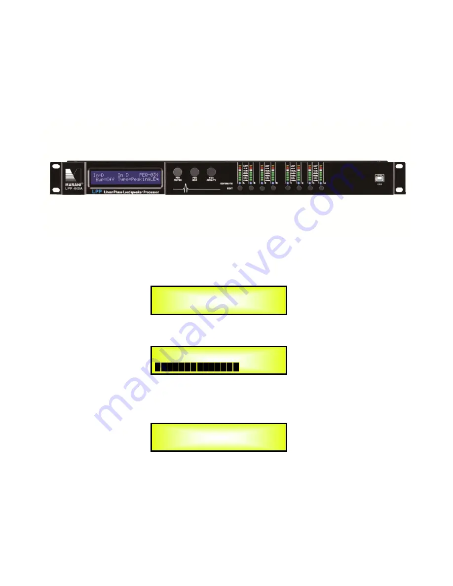
As soon as the LPP-440A is turned ON the device model name will appear in the LCD screen: 


and a status bar will show the progress of the LPP-440A initialization process:   


After the first time activation, the LPP-440A will show on the LCD : 


LPP-440A 

SPEAKER PROCESSOR 

LPP-440A 


LPP-440A 

P01: Default 

Summary of Contents for LPP-440A

Page 1: ...e LPP 440A Getting Started As soon as the LPP 440A is turned ON the device model name will appear in the LCD screen and a status bar will show the progress of the LPP 440A initialization process After the first time activation the LPP 440A will show on the LCD LPP 440A SPEAKER PROCESSOR LPP 440A LPP 440A P01 Default ...

Page 2: ...nd held for more than one second Input Channels A or B or C or D are either muted or unmuted The red LED will illuminate when the Channel is muted When the MUTE LED is OFF then the related Input Channel is UN MUTED A momentary push of the A B C and D buttons enters the Editing Mode for the Input Channels see later for the Input Channel Editing details The blue EDIT LED will now be ON When the 1 2 ...

Page 3: ...Y Recall a Program Recall a Program 01 Empty Program 16 Empty Program 2 2 PROGRAM UTILITY Save a Program Save a Program 01 Empty Program 16 Empty Program 2 3 PROGRAM UTILITY Delete a Program Delete a Program 01 Empty Program 16 Empty Program 3 UTILITY MENU Interface Utilities 3 1 INTERFACE UTILITY Interface Setup Interface Setup Source USB Source RS485 ID 1 32 Source TCP IP DHCP On Off Set IP addr...

Page 4: ... steps 10 4 us steps 480 0000mS 000 9984mS 5 In A B C D Name Phase Phase Normal Phase Normal PM1 N A Phase Normal Invert 6 In A B C D Name RMS Cmp Bypass On Bypass On PM1 N A Byp On Off PM1 N A Threshold 20dBu 10dBu PM1 N A Ratio 2 1 32 1 Knee 0 100 PM1 N A Rel 1ms 10 sec Atk 0 1ms 5000ms PM1 N A Make up 12dB 12dB 7 In A B C D Name EQ Byp Bypass On Bypass On PM1 N A Byp On Off 8 In A B C D Name PE...

Page 5: ... N A Frequency 20Hz 20000Hz Type Low Pass Q PM1 N A Frequency 20Hz 20000Hz PM1 N A Gain Fixed Q 0 1 5 1 Type Hi ghPass1 Hi ghPass2 PM1 N A Frequency 20Hz 20000Hz Type Hi ghPass Q PM1 N A Frequency 20Hz 20000Hz PM1 N A Gain Fixed Q 0 1 5 1 Type Band Pass PM1 N A Frequency 20Hz 20000Hz PM1 N A Gain 15dB 15dB Q 4 104 Type Notch Filt PM1 N A Frequency 20Hz 20000Hz PM1 N A Gain Fixed Q 4 104 Type All P...

Page 6: ... 0dB On PM1 N A 0 dB On Off 30Db 3 Output x Name Gain Gain 0 0 dB Gain 0 0 dB PM1 N A 18 dB 0 1dB 12dB 0 9dB Step 1dB Step 0 1dB 4 Output x Name Delay Delay 0 000 ms Delay 0 000 ms PM1 N A 000 0000mS 000 0000mS 1 ms steps 10 4 us steps 340 0000mS 000 9984Ms 5 Output x Name Phase Phase Normal Phase Normal PM1 N A Phase Normal Invert 6 Output x Name RMS Cmp Bypass On Bypass On PM1 N A Byp On Off PM1...

Page 7: ... Pass Notch Filt All Pass 1 All Pass 2 Type Peaking_Eq PM1 N A Frequency 20Hz 20000Hz PM1 N A Gain 15dB 15dB Q 0 4 128 Type Hi Shelv 1 Hi Shelv 2 PM1 N A Frequency 20Hz 20000Hz PM1 N A Gain 15dB 15dB Q Fixed Type Hi Shelv Q PM1 N A Frequency 20Hz 20000Hz PM1 N A Gain 15dB 15dB Q 0 1 5 1 Type Lo Shelv 1 Lo Shelv 2 PM1 N A Frequency 20Hz 20000Hz PM1 N A Gain 15dB 15dB Q Fixed Type Lo Shelv Q PM1 N A...

Page 8: ...to the LPP 440A Start Up and General Configuration UTILITY MENU From the System Utilities Sub menu pushing ENTER and then using the PM1 encoder for scrolling will give access to the following pages Input Source the LPP 440A is equipped with 4 Analog Inputs Balanced Female XLR and 2 AES Digital Input RCA connector and noise generator The Input Source page allows you to select the desired Input type...

Page 9: ...iseconds ms or Distance in meters m By pressing ENTER button and rotating the PM2 or PM3 encoder it is possible to select the measurement unit to be used for the delay which will be confirmed by pushing the ENTER button The following screen shows the selected delay measurement is Time milliseconds Set Default Value All setting for LPP 440A can be set to default value By pressing ENTER button will ...

Page 10: ...rogram by pressing the ENTER button You can store up to 16 presets in the LPP 440A memory By pressing ENTER button and rotating the PM1 encoders it is possible to scroll through all current available presets If NO USER PRESETS are stored yet the screen will show the following If presets have previously been stored by the user anyone of them can be recalled By using the PM1 encoder it is possible t...

Page 11: ...selected preset and the following transitory screen will appear Once loaded the LPP 440A will exit to the Recall a Program screen automatically and the above screen will disappear Note at any time it is possible to quit the recalling action by pressing the ESC button Loading New Program 01 PRESET 1 PROGRAM UTILITY Recall a Program ...

Page 12: ...e the User can set a Preset Name by using the PM3 encoder to choose a character and the PM2 encoder to move between the available locations for the character s positioning The following is an example of a screen while entering the preset name Stage 1 2x2 in location 10 To store the Preset Name press the ENTER button again The above action will take you to the Enter to Save page showing the selecte...

Page 13: ...age allows you to delete a preset already stored in the LPP 440A memory By pressing the ENTER button and rotating the PM1 encoder it is possible to scroll through the previously saved presets and the available empty locations identified by Program empty If no user presets are stored the Delete a Program screen will show empty memory locations for all 1 16 presets as shown in the example below for ...

Page 14: ...terface USB RS485 or TCP IP to be used for controlling the LPP 440A From Interface Utilities press ENTER button to access the Interface Setup Interface Setup this screen allows you to choose the communication source for the LPP 440A If select RS485 connect more than one unit under the RS485 mode By using PM3 encoder user can set the ID number from 1 to 32 to assign to the units connected and confi...

Page 15: ...he unit s functions and controls to those who have only access to the appropriate Password Press ENTER button and then use the PM1 encoder to scroll between options Show Parameter Pressing ENTER button from the above menu will access the Show Parameter Sub Menu Press ENTER button again and use the PM2 or PM3 encoders to select between be shown or not be shown options Choosing the be shown option m...

Page 16: ...LPP 440A is locked Change Password from the Change Password sub menu Press ENTER to access the Change Password page Use the PM2 encoder to move between available locations and the PM3 encoder to choose a character The current position of the cursor for the characters to be entered is shown by a blinking underscore Input the original password 000000 for the LPP 440A and press ENTER button will acce...

Page 17: ... s limitation to the editing function if the LPP 440A is locked with password All functions for this unit are banned including MUTE A B C D and MUTE 1 2 3 4 buttons Press ENTER to gain access to the Enter Password screen Use the PM2 encoder to move between available locations and rotate PM3 encoder to select characters If the password of this LPP 440A never modified input the default password 0000...

Page 18: ...rs the user desire by using 3 encoders Once the user leaves this page the above mentioned parameters would be saved to the LPP 440A systems automatically Remark 2 Exit this page by pressing ESC button Audio Signal Input A B C D Name page from this screen it is possible to assign input channel a name with 6 characters For example name the Input A as In L in the Name Page By pressing ENTER in the Na...

Page 19: ...alue set on this screen will only affect the input level of the selected Channel A The following is an example screen for the Gain page that has set the Gain of Input Channel A to 0 0dB Delay page from this page it is possible to set the Input Channels Delay Time from 000 0000mS up to 480 9984mS by steps of 1mS or 10 4uS To set the Delay time press ENTER an arrow will appear on the left of the scr...

Page 20: ...ack threshold can be set with PM2 or PM3 encoder with its range from 10dBu to 20dBu By rotating PM1 encoder one more time user can enter setting interface 3 of RMS Compressor RMS Compressor ratio can be set by PM2 encoder with its range rom 2 1 32 1 RMS Compressor knee can be set by PM3 encoder with its range from 0 100 By rotating PM1 encoder once again user can enter setting interface 4 of RMS C...

Page 21: ... ENTER in any parametric equalization page an arrow will appear on the left of the screen then enter setting interface 1 of parametric equalization filter By using PM2 encoder it is possible to set the flat on or off for the current parametric equalization filter By using PM3 encoder user can set the current parametric equalization filter s type selectable as Peaking_Eq Hi Shelv 1 Hi Shelv 2 Hi Sh...

Page 22: ...is possible to set current input PEQ filter s frequency from the range of 20Hz to 20kHz By rotaing PM1 encoder again user can enter the setting interface 5 of current input parametric equalization filter By using PM2 or PM3 encoder user can set the gain of current parametric equalization filter from 15dB to 15dB When the parametric equalization filter is selected as Hi Shelv Q Lo Shelv Q by rotain...

Page 23: ...from the range of 20Hz to 20kHz By rotaing PM1 encoder again user can enter the setting interface 10 of current input parametric equalization filter By using PM2 or PM3 encoder it is possible to set the Q factor of current parametric equalization filter from 0 1 to 5 1 When the parametric equalization filter is selected as Band Pass by rotaing PM1 encoder user can enter the setting interface 11 of...

Page 24: ...nput PEQ filter s frequency from the range of 20Hz to 20kHz When the parametric equalization filter is selected as All Pass 2 by rotaing PM1 encoder user can enter the setting interface 16 of current input parametric equalization filter By using PM2 or PM3 encoder it is possible to set current input PEQ filter s frequency from the range of 20Hz to 20kHz By rotaing PM1 encoder again user can enter ...

Page 25: ...ected option is AUTOMATICALLY loaded during the encoders use and stored as the current value once leaving the page Audio Signal Output 1 2 3 4 Name page from this screen it is possible to assign output channel a name with 6 characters For example name the Output 1 as Low in the Name Page By pressing ENTER in the Name page user can edit the name and there will be an arrow as the following screen sh...

Page 26: ...84mS by steps of 1mS or 10 4us To set the Delay time press ENTER button an arrow will appear on the left of the screen then use the PM2 encoder to set the Delay Time in steps of 1mS and the PM3 for setting the fine Delay Time in steps of 10 4 microseconds The following is an example screen for the Delay page where the Delay Time of Output Channel 1 is set to 160 1872mS Phase page from this page it...

Page 27: ...ting interface 4 of RMS Comp User can set RMS Cmp s release time from 1ms to 10 sec by using PM2 encoder and set its attack time by using PM3 from 0 1ms to 5ms By rotating PM1 encoder will enter into the setting interface 5 of RMS Comp By using PM2 and PM3 encoders user can set the RMS Cmp s make up from 12dBu to 12dBu Limiter page from this page it is possible to set the Output Channels Limiter L...

Page 28: ...eft of the screen then enter into the setting interface 1 of High Pass filter By using PM2 or PM3 encoder it is possible to set output channels High Pass filter frequency from 20Hz to 20kHz By rotating PM1 encoder it will enter setting interface 2 of High Pass filter By using PM2 or PM3 encoder it is possible to set the High Pass filter s shape and order of the output High Pass filter Following is...

Page 29: ...t LR 24 dB Oct BS 24 dB Oct BW 36 dB Oct LR 36 dB Oct BW 48 dB Oct LR 48 dB Oct EQ Byp page in this page it is possible to set EQ Bypass of output channels with its selectable status of ON and OFF Following is the example screen as Bypass ON By pressing ENTER in this page an arrow will appear on the left of the screen then enter setting interface of EQ Bypass By using PM2 or PM3 encoder user can s...

Page 30: ...of 20Hz to 20kHz By rotaing PM1 encoder again user can enter the setting interface 3 of current input parametric equalization filter By using PM2 encoder user can set the gain of current parametric equalization filter from 15dB to 15dB and by using PM3 encoder it is possible to set the Q factor of current parametric equalization filter from 0 4 to 128 When the parametric equalization filter type i...

Page 31: ...Pass 2 by rotaing PM1 encoder again user can enter the setting interface 8 of current output parametric equalization filter By using PM2 or PM3 encoder it is possible to set current output PEQ filter s frequency from the range of 20Hz to 20kHz When the parametric equalization filter type is selected as Low Pass Q High Pass Q by rotaing PM1 encoder again user can enter the setting interface 9 of cu...

Page 32: ...tion filter By using PM2 or PM3 encoder it is possible to set current output PEQ filter s frequency from the range of 20Hz to 20kHz By rotaing PM1 encoder again user can enter the setting interface 14 of current input parametric equalization filter By using PM2 or PM3 encoder it is possible to set the Q factor of current parametric equalization filter from 4 to 104 When the parametric equalization...

Page 33: ...filter By using PM2 or PM3 encoder it is possible to set the Q factor of current parametric equalization filter from 4 to 104 Note 1 After selected the desired choice with 3 encoders the choice would be set as the current one for the unit automatically and would be stored in the LPP 440A system when user quits this page Note 2 By pressing ESC to quit this page Out 1 Out 1 PEQ 01 Frequency 20Hz Out...

Page 34: ...n link the Slaves by pressing their related Edit buttons All Linked channels will be selected ready for adjustment when their Blue LED is lit in the Editing mode Now all Slave channels and only those selected will modify their parameters accordingly as you edit the Master channel All other existing parameters will stay the same within the Slave Channels unless edited by this link with the Master c...

Page 35: ...red information and changed parameters will be permanently lost Use the following procedure to perform the factory reset 1 While the LPP 440A is switched OFF simultaneously press the ENTER ESC UTILITY buttons on the front panel 2 Maintain pressure on all three buttons as you turn the power switch to On and the following LCD screen appears on the LPP 440A 3 Release the buttons and wait for the LPP ...

Page 36: ...llowing Click the UTILITY button showing the first class content of the primary menue please refer to the following picture Rotate NAV PM1 encoder to change the primary menue as the following content 1 2 push ENTER button LCD shows as the below display reflecting the way how unit is connected with computer Rotate PM2 and PM3 encoder to change the interface as to the following display push ENTER bu...

Page 37: ...need to capture from the router in its connected network 2 Set the connection condition of PC take XP for example Enter the PC s controlling Pannel network connect local open the dialogue box of Properties please refer to the following picture Select Internet Protocol TCP IP in use the following subjects under this connection 0 and click the attribute bottom marked in the red envelop in below imag...

Page 38: ... set the IP address display the set PC IP Host Address 192 168 0 2 Set the IP device same as the IP address of the LPP 440A Note that in the example the IP address of LPP 440A is set as 192 168 0 100 so the IP address shall be set as 192 168 0 100 please refer to the following picture Click the in the above image will show the following interface which means that the LPP 440A already connected to ...

Page 39: ...Analog Input Signal ChA ChB ChC ChD Bal Female XLR Maximum Input Level 20dBu Analog Output Signal Ch1 Ch2 Ch3 Ch4 Bal Male XLR Maximum Output Level 20dBu Sampling Frequency 96kHz FIR Sampling Frequency 48kHz S N 110dBA THD N 0 005 Frequency Response Bypass 20Hz 20kHz 1 dB Power Supply Switching Power Supply Remote Control USB RS485 TCP IP ...

Reviews: