Continuous Rating (W)
Voltage (V)
Cycle (Hz)
Input
Output
Max. Output(W)
110
400
2,000
2,000
Yes (Rocker type)
350 (260)
400
400
400
400
230
230
230
230
230
350
350
350
350
350
120
220
230
240
3.8
3.5
1.9
1.8
1.8
12.7 (1/2)
2.5 (8.2) for other than Australia
2.0 (6.6) for Australia
2.9 (6.4)
M12 - M22
M12 - M16
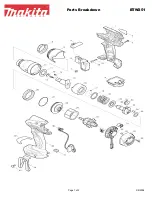
Models No.
Description
PRODUCT
Current (A)
T
ECHNICAL INFORMATION
C
ONCEPTION AND MAIN APPLICATIONS
S
pecification
S
tandard equipment
O
ptional accessories
< Note > The standard equipment for the tool shown may differ from country to country.
P 1 / 8
Dimensions : mm ( " )
Width ( W )
Height ( H )
Length ( L )
TW0350
Impact Wrench
50 / 60
50 / 60
50 / 60
50 / 60
50 / 60
283 (11-1/8)
233 (9-1/8)
87 (3-7/16)
* Socket 24-45 .................................... 1 pc.
* Plastic carrying case ....................... 1 pc.
* Socket 19-38
* Socket 19-52
* Socket 19-78
* Socket 21-38
* Socket 21-52
* Socket 21-78
* Socket 21-150
* Socket 22-38
* Socket 22-52
* Socket 23-38
* Socket 23-52
* Socket 24-45
* Socket 24-52
* Socket 26-50
* Socket 26-78
* Socket 27-50
* Socket 27-78
* Socket 30-50
* Socket 30-78
* Socket 32-50
* Socket 32-78
Max. fastening torque : N.m (ft.lbs)
Reverse switch
Net weight: kg (lbs)
No load speed (min
-1
=rpm)
Impact per minute (min
-1
=bpm)
Square drive : mm ( " )
Capacities
Power supply cord : m ( ft )
High Tensile bolt
Standard bolt
L
H
W
In order to occupy the advantageous position in the market,
we have developed the above impact wrench with the following
features.
* Incredibly high torque of 350 N.m (260 ft.lbs)
* Equipped with palm-fitting soft grip for comfortable work.
* Extension bar
* Universal joint
* Elliptic socket
* Time switch