Models No.
Description
PRODUCT
C
ONCEPT AND MAIN APPLICATIONS
S
pecification
P 1/ 9
L
H
W
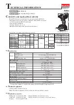
BTL060/ BTL061
Cordless Angle Impact Drivers 14.4V/ 18V
Models BTL060 and BTL061 have been developed as advanced
models of 6940D.
Additionally to the same high fastening performance and
compact angle head as Model 6940D, feature soft grip and
LED job light for more maneuverability in tight places.
This product is available in the following variations.
BTL060
BTL061
Model
Specifications
Dimensions: mm (")
Width (W)
Height (H)
Length (L)
387 (15-1/4)
97 (3-13/16) 116 (4-9/16)
78 (3-1/16)
BTL060
BTL061
BTL060
BTL061
Battery
No load speed: min.-
1
=rpm
Impacts per min.: min.-1=ipm
Max. fastening torque: N.m [kgf.cm] (in.lbs)
Capacities
Electric brake
Reverse switch
Net weight: kg (lbs)
Variable speed control by trigger
Capacity: Ah
Cell
Voltage: V
18
14.4
0 - 2,000
0 - 3,000
60 [610] (530)
Standard bolt
High tensile bolt
Machine screw
Driving shank
M4 - M12 (5/32 - 7/16")
M4 - M8 (5/32 - 5/16")
Coarse thread screw
22 - 75mm (7/8 - 2-31/32")
M4 - M8 (5/32 - 5/16")
Yes
Yes
Yes
1.6 (3.5)*
1
1.7 (3.7)*
2
3.0
Li-ion
110
120
6.35mm (1/4") Hex
Max output (W)
*1: with Battery BL1430 *2: with Battery BL1830
T
ECHNICAL INFORMATION
22
with DC18RA
LED Job light
See next page for Standard equipment and Optional accessories.
Yes
Charging time: min.
All models also include the accessories listed in "Standard equipment" on next page.
BTL060
BTL060RFE
BTL060Z
BTL060
BL1430
(Li-ion 3.0Ah)
DC18RA
No
No
No
Model No.
type
quantity
Charger
Yes
No
Plastic
carrying case
Offered to
All countries
North America
All countries except North America
2
BTL060RF
1
1
No
Battery
Battery
cover
BTL061
BTL061RFE
BTL061Z
BTL061
BL1830
(Li-ion 3.0Ah)
DC18RA
No
No
No
Model No.
type
quantity
Charger
Yes
No
Plastic
carrying case
Offered to
All countries
North America
All countries except North America
2
BTL061RF
1
1
No
Battery
Battery
cover