Maco Antennas M103C, Assembly Instructions Manual
The Maco Antennas M103C Assembly Instructions Manual provides step-by-step guidance for effortless assembly of our high-quality antenna. This comprehensive manual is available for free download on our website, ensuring you have all the necessary instructions to set up your antenna quickly and efficiently.
Share
Download


Reviews:
No comments
Related manuals for M103C
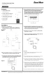
FLATenna
Brand: Channel Master Pages: 2

ACC-A24R-S
Brand: albentia Pages: 2

TXWF-PCB-3214
Brand: Ebyte Pages: 6

Precision MXL012/55NZ
Brand: Maxview Pages: 12

27885D/01
Brand: Philex Pages: 8

4-8 PRO
Brand: Hi-Z Antennas Pages: 15

TRKS26
Brand: DirecTV Pages: 1

EMV1200 HD
Brand: EverFocus Pages: 12

D Series
Brand: Megasat Pages: 17

Classic
Brand: Megasat Pages: 11

Countryman GPS
Brand: Megasat Pages: 44

1500178
Brand: Megasat Pages: 32

010-00730-00
Brand: Garmin Pages: 48

CMAX-DMW3060-43i53
Brand: CommScope Pages: 8

SK-1000
Brand: Winegard Pages: 27

XH2-120
Brand: Xirrus Pages: 27

HAO9SDP
Brand: Hawking Pages: 2

AS-3226C/URC
Brand: Valcom Pages: 19


