background image


M2 Antenna Systems, Inc. 4402 N. Selland Ave. Fresno, CA 93722 

Tel: (559) 432-8873 Fax: (559) 432-3059 Web: www.m2inc.com 

©2015 M2 Antenna Systems Incoporated 

06/09/15 

Rev.01 

Model  ......................................... 6-30LP11 
Frequency Range ....................... 6 To 30 MHz 

*

Gain .......................................... 5 To 6.2 dBi 

Front to back .............................. 10 To 20 dB Typical 
Feed Impedance. ....................... 50 Ohms Unbalanced


Maximum VSWR ........................ 1.8:1 Max, Under 1.5 


Input Connector .......................... “N” Female 
Power Handling .......................... 3 Kw, Higher Optional 
Boom Length / Type ................... 80’ / Steel Tower  
Turning Radius: .......................... 65’ 
Wind area / Survival ................... 125 MPH 
Weight / Ship Wt. ........................ 1,228 Lbs. 


M2 Antenna Systems, Inc. 

Model No: 6-30LP11 

FEATURES: 


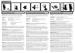
The 6-30lp11 log periodic is a modern design both mechanically and electrically.  Top quality materials combined 

with many CNC machined parts will keep it trouble free for years or operation. Performance is excellent and specific path 
gain can be as much as 12 dB with ground gain factored in. The 6-30LP11 is available individually or in a turnkey system, 
complete with support tower, rotation mechanism and controller. Many options exist within the turnkey system such as 
height and type of tower, rotator mechanism, and controller type. As pictured above and originally supplied to NASA at 
Edwards air Force Base in Edwards California, the tower was a special, massive, motorized, self supporting 72 foot tower 
supplied by US tower Corp to M

2

 specifications. The 6-30LP11 is the latest Log to join the M

2

 Family of high quality broad 

band antennas. 

SPECIFICATIONS: 

*Subtract 2.14 from dBi for dBd 

Summary of Contents for 6-30LP11

Page 1: ...trically Top quality materials combined with many CNC machined parts will keep it trouble free for years or operation Performance is excellent and specific path gain can be as much as 12 dB with groun...

Page 2: ...nd position it about 3 4 inside the other 1 4 hole Repeat this for all five of the 7 8 FIBERGLASS RODS Slight repositioning of the poly discs may be required when the element is mounted below the boom...

Page 3: ...8 OUTSIDE SLEEVE over the butt section to maintain element strength to survive 125 mph winds ELEMENT 4 is unique because at 4 there is transition in phasing line diameter Both PHASE LINE CLAMPS AND 3...

Page 4: ...reign substances that could conduct under the right condition 8 Assembling ELEMENT 2 1 is similar to 3 except ELEMENT 2 1 each use 2 ELEMENT SIDE SUPPORT BRACKETS that are attached to the 2 sections j...

Page 5: ...2 grade 5 galvanized bolts 1 2 13 galvanized nut 1 2 13 galvanized pal nut for all tower boom section joints 2 Shims as shown are supplied with tower sections to help align Use as needed 6 30LP11 BOOM...

Page 6: ...6 30LP11 ELEMENT ASSEMBLY 4 11...

Page 7: ...6 30LP11 ELEMENT ASSEMBLY 3...

Page 8: ...6 30LP11 ELEMENT ASSEMBLY 2...

Page 9: ...6 30LP11 ELEMENT ASSEMBLY 1...

Page 10: ...fiberglass rods and 4 HD CRADLES with 1 1 4 radius Use 5 16 24 x 4 1 2 bolts and locknuts 5 Because of their size and weight we have suggested that just the INNER SECTIONS of element 3 2 and 1 be moun...

Page 11: ...kle eye and over the cable eye Push the cable end back through the clips pull all the slack out of the cable and then push one clip close against the cable eye and begin tightening the nuts on the cli...

Page 12: ...t PHASE LINE CLAMPS only 3 Continue by adding the next set of phasing lines between element 10 and 9 Center align the phasing rods and tighten the PHASE LINE CLAMPS on element 10 Contin ue installing...

Page 13: ...o pairs of 3 8 PHASE LINE CLAMP CAPS on the element butts If not then add them now loosely Continue installing this phase line set using eight 8 3 8 PHASE LINE SUPPORT INSULATORS Center and align the...

Page 14: ...boom itself Slide two 3 8 cable clips on a cable end and route the cable through the turnbuckle over the cable eye and back through the two clips Slide one clip against the cable eye and begin tighte...

Page 15: ...INSULATOR 2 I D 2 CRADLE 2 HD MACH ALUM 8 ELEMENT VERTICAL SUPPORT MAST 1 1 2 X 48 WELDED 1 ELEMENT VERTICAL SUPPORT BRACKET STEEL WELDED 1 ELEMENT SIDE SUPPORT BRACKET ALUMINUM WELDED 2 3 8 PHASE LIN...

Page 16: ...INSULATOR 2 I D 2 CRADLE 2 HD MACH ALUM 4 ELEMENT VERTICAL SUPPORT MAST 1 1 2 X 48 WELDED 1 ELEMENT VERTICAL SUPPORT BRACKET STEEL WELDED 1 ELEMENT SIDE SUPPORT BRACKET WELDED 2 3 8 PHASE LINE CLAMP...

Page 17: ...7 8 X 058 X 71 875 6063 T832 2 ELE 3 SEC 7 3 4 X 049 X 81 SOE 6063 T832 2 ELE 3 SEC 8 1 2 X 049 X 63 6063 T832 2 CENTER SUPPORT INSUL 2 X 36 W COUPLING RINGS 1 POLY DISC INSULATOR 2 I D 2 CRADLE 2 HD...

Page 18: ...T MAST 1 2 X 180 X 96 GALV GUY CABLE HPTG 6700 PHILISTRAN X 70 FT 1 TURNBUCKLE 1 2 X 12 FORGED GALV 2 CRADLE 1 1 2 MACHINED ALUM 13 32 HOLES 16 TOWER SHIM THICK 12 TOWER SHIM THIN 12 HARDWARE BOLT 1 2...

Page 19: ...T6 2 3 16 X ROD BENT 6061 T6 2 PHASE LINE SUPPORT INSULATOR FOR 3 8 TUBE 24 PHASE LINE SUPPORT INSULATOR FOR 3 16 ROD 20 PHASE LINE SUPPORT CAP DELRIN 44 375 PHASE LINE SPACER 3 4 X 2 X 2 DELRIN 3 18...

Page 20: ...1 1 X 058 X 60 SOE 1 4 HOLE 8 ELE 6 SEC 2 1 X 058 X 60 SOE 2 HOLES 2 ELE 4 SEC 4 1 X 058 X 39 SOE 4 SLEEVE 7 8 X 058 X 15 2 ELE 8 SEC 2 3 4 X 049 X 63 STR 2 ELE 9 SEC 2 3 4 X 049 X 39 25 STR 2 ELE 4 S...

Page 21: ...20 X 1 1 2 SS 10 SCREW 1 4 20 X 1 FH SS 16 NUT LOCKING 1 4 20 SS 32 SCREW 8 32 X 2 SS 10 SCREW 8 32 X 1 3 4 SS 10 SCREW 8 32 X 1 1 2 SS 22 SCREW 8 32 X 1 1 4 SS 28 SCREW 8 32 X 1 SS 16 LOCKNUT 8 32 SS...

Page 22: ...6 30LP11 PARTS IDENTIFICATION...

Page 23: ...20 X 2 1 4 SS 4 BOLT 1 4 20 X 2 SS 2 BOLT 1 4 20 X 1 1 2 SS 4 SCREW FLATHEAD 1 4 20 X 1 SS 4 NUT LOCKING 1 4 20 SS 24 SCREW 8 32 X 2 1 4 SS 2 SCREW 8 32 X 2 SS 4 SCREW 8 32 X 1 3 4 SS 4 SCREW 8 32 X...

Reviews: