background image

Symmetric Quadruped Robot Kit Assembly 

Instructions Rev. 1.

Safety first! 

Wear eye protection and never 

touch a powered robot!

The purpose of this guide is to construct the 

chassis, attach the legs, and install the 
electronics. Both the top and bottom body plates 

are identical. This guide shows the PS2 receiver 
and plate which are purchased separately from 

the kit.

Image of completed Robot.

(Shown with optional PS2 receiver and mount)

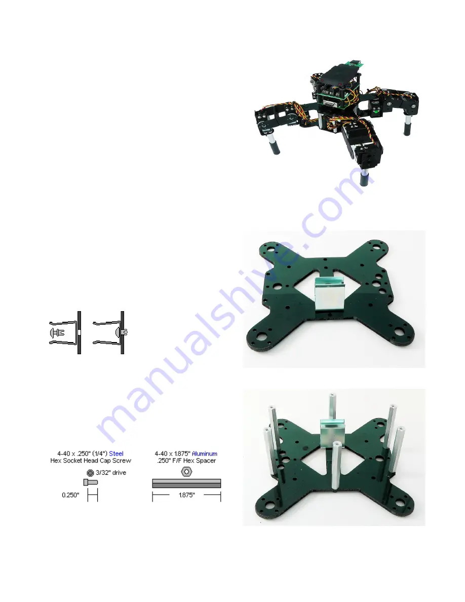
Step 1. Build the Lower Body.

Both the top plate and bottom plate are identical. 

Place the small black rivet through the 9V metal 
clip and push down through one of the two inner 

holes as shown. It does not matter which side. 
This will become the bottom plate.

1 x

Figure 1.

Step 2.

Use six 4-40 x 1/4" hex socket screws to attach 
the long aluminum spacers to the bottom body 

plate.

6 x

6 x

Figure 2.

Summary of Contents for Symmetric Quadruped Robot Kit

Page 1: ...d plate which are purchased separately from the kit Image of completed Robot Shown with optional PS2 receiver and mount Step 1 Build the Lower Body Both the top plate and bottom plate are identical Place the small black rivet through the 9V metal clip and push down through one of the two inner holes as shown It does not matter which side This will become the bottom plate 1 x Figure 1 Step 2 Use si...

Page 2: ...h connects to which hole Figure 4 Step 5 Attach the legs as shown making sure to use right or left legs as indicated Use eight 2 x 250 tapping screws two per servo The legs should be positioned at 45 degrees to the body and the servo should be receiving a 1500us pulse so the servo is positioned at 90 degrees If you are unsude how to do this please refer back to the leg assembly guide In order to u...

Page 3: ...ERMINALS the red wire should go to and the black wire to if they are reversed the servos and the board will be damaged Figure 6 Step 7 SSC 32 Bluetooth This approach applies if you plan to control the robot from the computer using a Bluetooth device as is the case with FlowBotics Studio Attach the power cables as shown in Figure 7b Install the SSC 32 onto the body using four 1 4 4 40 hex screws Co...

Page 4: ... check your connections against the figure below Be sure that red wires go to positive and black wires go to negative Also be sure that your jumpers are connected the exact same way as detailed below Note that the VL VS jumper on the SSC 32 is removed as are the Tx and Rx jumpers Depending on the configuration and code you may also need to change the baud rate jumpers The sample code for the BotBo...

Page 5: ...ctronics and turn the On Off switch to On You should see the green LED in the upper right corner of the SSC 32 switch on There is also a power LED on the BotBoarduino If these LEDs do not switch on IMMEDIATELY power off your robot and double check your connections Remove the 9v battery from the clip before moving on ...

Page 6: ...ext tutorial Figure 10 Step 12 Mount the SSC 32 onto the four hex spacers used in step 3 Use four 4 40 x 1 hex spacers to attach the long aluminum spacers to the underside of the top body plate The figure does not show the wiring for clarity 4 x Figure 12 Mount the SSC 32 wires etc removed for clarity Step 13 Use four 4 40 x 1 4 hex socket screws to mount the BotBoarduino to the hex spacers in the...

Page 7: ...e SSC 32 user guide for more information You will need to add the position offset commands in the sample code Step 14c If you have FlowBotics Studio pair with the Bluetooth module via the FlowBotics Studio SQ3 project interface The green light on the Bluetooth will become solid once a connection has been established Click the configure button to position each of the servos to exactly 90 degree Ste...

Reviews: