background image

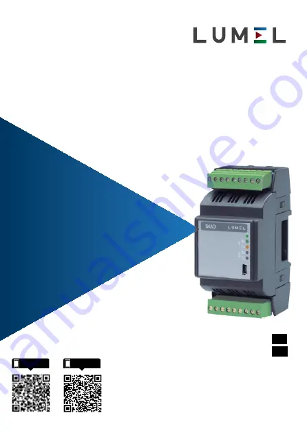
MODUŁ 4 WYJŚĆ ANALOGOWYCH 

MODULE OF 4 ANALOG OUTPUTS

S4AO

INSTRUKCJA OBSŁUGI - SZYBKI  START

Pełna wersja instrukcji dostępna na

Full version of user’s manual available at  

www.lumel.com.pl

USER’S MANUAL - QUICK START

PL

EN

Zeskanuj mnie

Zeskanuj kod

Scan the code

Summary of Contents for S4AO

Page 1: ...DULE OF 4 ANALOG OUTPUTS S4AO INSTRUKCJA OBSŁUGI SZYBKI START Pełna wersja instrukcji dostępna na Full version of user s manual available at www lumel com pl USER S MANUAL QUICK START PL EN Zeskanuj mnie Zeskanuj kod Scan the code ...

Page 2: ...iami Uwagi dotyczące bezpieczeństwa Instalacji i podłączeń elektrycznych powinien dokonywać wykwalifikowany personel Należy wziąć pod uwagę wszystkie dostępne wymogi ochrony Przed włączeniem urządzenia należy sprawdzić poprawność połączeń Otwarcie obudowy urządzenie daje dostęp do elementów pod napięciem Przed zdjęciem obudowy urządzenia należy wyłączyć jego zasilanie oraz odłączyć obwody wyjściow...

Page 3: ...rzymanie wyjścia napięciowego w stanie zwarcia powodu je nagrzewanie się modułu co może powodować problemy z komunikacją poprzez RS 485 2 MONTAŻ 2 1 Sposób mocowania Moduł S4AO może zostać zamontowany w moduło wych urządzeniach dystrybucyjnych na wsporniku szynowym 35 mm Obudowa modułu wykonana jest z tworzywa sztucznego o wy miarach 53 x 110 x 60 5 mm Na zewnątrz modułu znajdują się listwy zacisk...

Page 4: ...4 pl 2 2 Schematy podłączeñ zewnêtrznych Patrz rys 3 4 str 31 2 3 Złącze boczne Patrz rys 5 str 34 Rys 1 Wymiary gabarytowe modułu ...

Page 5: ... RS 485 nr 1 i 2 muszą być skonfigurowane Tabela 4 Rejestry 4000 Modbus patrz pełna wersja instrukcji obsługi a urządzenie musi być zasilane 3 2 Działanie modułu w trybie Slave Aby moduł S4AO mógł zostać wykorzystany w trybie Slave na interfejsie RS 485 musi zostać on skonfigurowany w nastę pujący sposób tryb portu RS 485 nr 1 rejestr 4010 lub tryb portu RS 485 nr 2 rejestr 4017 ustawiony jako 0 S...

Page 6: ...ransmisji prędkość transmisji okres skanowania i wartości przekroczenia limitu czasu rejestry 4011 do 4022 i zmian aktualizacji rejestr 4016 dla portu nr 1 4023 dla portu nr 2 dla każdego z wybranych wyjść należy ustawić parametry charakterystyki indywidualnej rejestry 7620 do 7635 lub ich odpowiedniki 16 bitowe z grupy 6000 7000 tryb sterowania Master rejestry 4132 do 4135 adres rejestr wartość p...

Page 7: ...ź interfejsu RS 485 Po uruchomieniu programu eCon należy wybrać port na którym zainstalowano urządzenie w części Komunikacja ustawić parametry komunikacji domyślnie prędkość 9600 tryb RTU 8N2 a następnie kliknąć ikonę połącz Przed zmianą konfiguracji należy odczytać i zapisać bieżącą konfigurację aby umożliwić późniejsze odzyskanie ustawień Z menu programu eCon możliwe jest zapisanie parametrów do...

Page 8: ...konfiguracji do pliku pdf Odczyt konfiguracji z pliku pdf Zapis konfiguracji w przetworniku Odczyt konfiguracji z przetwornika Informacja o module Rys 7 Zapis wczytanie i eksport ustawień połącz rozłącz Rys 8 Nawiązywanie połączenia z modułem S4AO ...

Page 9: ...rt 1 Slave lub Master Slave Master Slave Tryb transmisji Wybór trybu transmisji zewnętrznego RS 485 Port 1 8N2 8E1 8O1 8N1 8N2 Prędkość transmisji Wybór prędkości trans misji zewnętrznego RS 485 Port 1 1 200 2 400 4 800 9 600 19 200 38 400 57 600 115 200 9 600 Modbus Ma ster przekro czenie limitu czasu urządze nia slave Czas po którym ser wer Master uznaje że wywoływane urządze nie nie odpowiada 0...

Page 10: ... 8N1 8N2 Prędkość transmisji Wybór prędkości trans misji zewnętrznego RS 485 Port 2 1 200 2 400 4 800 9 600 19 200 38 400 57 600 115 200 9 600 Modbus Ma ster przekro czenie limitu czasu urządze nia slave Czas po którym ser wer Master uznaje że wywoływane urządze nie nie odpowiada 0 1 5 s 0 5 s Modbus Master czas skanowania urządzenia slave Czas pomiędzy po szczególnymi zapyta niami serwera Master ...

Page 11: ...ryb Master odczyt przez zewn RS 485 Tryb Master odczyt przez wewn RS 485 Tryb Slave Próg dolny Kiedy wartość na wyj ściu analogowym jest niższa niż ta wartość wartość odpowiedniego licznika jest zwiększa na co sekundę 0 00 24 00mA prąd 0 00 12 00 V napięcie 0 00 Próg górny Kiedy wartość na wyj ściu analogowym jest wyższa niż ta wartość wartość odpowiedniego licznika jest zwiększa na co sekundę 0 0...

Page 12: ...olu Przekroczenie limitu czasu 0 00 24 00mA prąd 0 00 12 00 V napięcie 0 00 Przekroczenie limitu czasu Wartość przekroczenia limitu czasu Wyjście analogowe ustawi war tość alarmu jeżeli nie zostanie zaktualizowa ne po upływie ustalo nego czasu Funkcja ta jest wyłączana poprzez ustawienie wartości równej 0 0 0 0 3 000 0 s 0 0 s Zakres wyjścio wy prądowy Tylko wyjście prądowe Określa zakres warto śc...

Page 13: ...ych do odczytu z urządzenia Slave char 8 uchar 8 short 16 ushort 16 long 32 ulong 32 float 32 float 2x16 3210 float 2x16 1010 long 2x16 swapped long 2x16 ulong 2x16 u swapped long 2x16 char 8 X0 Tylko tryb Master Cha rakterystyka indywidu alna punkt X0 odczyt przez Modbus RS 485 Master 3 40282347E 38 3 40282347E 38 0 X1 Tylko tryb Master Cha rakterystyka indywidu alna punkt X1 odczyt przez Modbus ...

Page 14: ...granic Wersjewyposażonewwyjścienapięciowemogątakżewskazywaćczas przez który było zwarcie w każdym układzie wyjść Device status Stan urządzenia Zakładka ta pokazuje parametry S4AO Wartości stanu W oknie wyświetlane są wartości bieżące napięcia prądu na wyjściach odczytane przez urządzenie RS 485 Master jeśli jest włączone możliwe jest też ręczna aktualizacja każdej wartości wyjściowej Wartości skon...

Page 15: ...sy szeregowe RS485 adres 1 247 tryb 8N2 8E1 8O1 8N1 prędkość transmisji 1 2 2 4 4 8 9 6 19 2 38 4 57 6 115 2 kbit s Należy używać wyłącznie przewodów ekranowanych USB dla konfiguracji 1 1 2 0 adresy wszystkie tryb wszystkie prędkość transmisji wszystkie maksymal na długość przewodu USB 3m adres komunikacji 253 tryb transmisji Modbus RTU maks czas rozpoczęcia odpowiedzi 400 ms odczyt 1000 ms zapis ...

Page 16: ...rzechowywania 25 70 C wilgotność 95 niedopuszczalna kondensacja zewnętrzne pole magnetyczne 0 40 400 A m pozycja pracy pionowa czas wstępnego wygrzewania 30 min Kompatybilność elektromagnetyczna odporność na zakłócenia elektromagnetyczne wg PN EN 61000 6 2 emisja zakłóceń elektromagnetycznych wg PN EN 61000 6 4 Wymagania bezpieczeństwa według normy PN EN 61010 1 izolacja między obwodami podstawowa...

Page 17: ...ase of ignoring information In terms of operational safety the meter meets the requirements of the EN 61010 1 2011 standard Comments concerning safety Assembly and installation of the electrical connections should be conducted only by people authorized to perform assembly of electric devices The person installing the device is responsible for ensuring the safety of the implemented system Always ch...

Page 18: ...or using the device in a way which is not compliant with the user s manual may cause deterioration of the degree of protection Maintaining a voltage output on short cicuit state will make an overheating of the module and can cause troubles on RS 485 communications 2 INSTALLATION 2 1 Mounting The S4AO module can be installed in modular distribu tion devices on the 35 mm rail bracket The module encl...

Page 19: ...EN 19 2 2 Connection Diagrams See fig 2 3 page 31 Figure 1 Module dimensions 2 3 Lateral bus See fig 4 page 34 ...

Page 20: ...to get 5 00 V on a voltage output write 500 on the corresponding register Note that on start each output is set to its alarm value re gister 4112 to 4115 Eventually set the high and low value threshold to start the high and low value counters registers 4104 to 4111 and reset them registers 4162 to 4170 3 OPERATION 3 1 Configuration The S4AO module can be configured by Modbus protocol through 3 int...

Page 21: ...23 for port 2 For each selected output set the individual characterisitc s parameters register 7620 to 7635 or their 16 bit equiva lents from the group 6000 7000 the Master controlled mode register 4132 to 4135 the address the register the timeout and the type to read register 4136 to 4159 The read value as displayed as floats in the 7600 to 7603 registers or in their 16 bit equivalents from the g...

Page 22: ...e RS 485 interface When the e Con program starts select the port on which the device is installed in the area Communication set the transmission parameters baud rate 9600 mode RTU 8N2 by default and then click the icon connect Before changing a configuration you should read and save the current configuration for future restoring of the settings You can save the parameters to a file read from a fil...

Page 23: ...uration to a file Reading the configuration from file Saving the configuration to a meter Reading the configuration from a mete Information about the module Figure 6 Read write and export settings connect disconnect Figure 7 Establishing connection to S4AO module ...

Page 24: ...ter Slave Master Slave Transmission mode Choice of the external RS 485 Port 1 trans mission mode 8N2 8E1 8O1 8N1 8N2 Baud rate Choice of the baud rate of the external RS 485 Port 1 baud rate 1 200 2 400 4 800 9 600 19 200 38 400 57 600 115 200 9 600 Modbus Master slave response timeout Timeout after which the Master server considers that the interrogated device will not reply 0 1 5 s 0 5 s Modbus ...

Page 25: ... the Master server considers that the interrogated device will not reply 0 1 5 s 0 5 s Modbus Master slave scanning period Time between each pool from the Master server 0 1 30 000 s 0 5 s Modbus slave address Modbus address of the interface when used as Slave 1 247 2 Analog output 1 2 3 and 4 tab Mode Settings the way which the output is controlled directly by an Modbus interface as Slave or by an...

Page 26: ...ase of power on and timeout The analog output will take this value when the module turns on or if the output is not refreshed by an external Modbus Master or an integrated Master server after a time specified in the Timeout field 0 00 24 00 mA current 0 00 12 00 V voltage 0 00 Timeout Timeout value The analog output will take the alarm value if is not updated after the set time This feature is dis...

Page 27: ...ong 32 ulong 32 float 32 float 2x16 3210 float 2x16 1010 long 2x16 swapped long 2x16 ulong 2x16 u swapped long 2x16 char 8 X0 Master mode only In dividual characteristic point X0 read through Modbus RS 485 Master 3 40282347E 38 3 40282347E 38 0 00 X1 Master mode only In dividual characteristic point X1 read through Modbus RS 485 Master 3 40282347E 38 3 40282347E 38 1 00 Y0 Master mode only Individ...

Page 28: ... a short circuit was detected on each output set Device status This tab is used to show on one window the parameters of the S4AO Status values This window show the current voltage current va lue at the outputs the value read by RS 485 Master if enabled and allow also to update manually each output Configured values This window shows for each output the read value through Master if enabled the time...

Page 29: ...ode 8N2 8E1 8O1 8N1 baud rate 1 2 2 4 4 8 9 6 19 2 38 4 57 6 115 2 kbit s Use only shielded cable USB for configuration 1 1 2 0 address all mode all baud rate all maximal USB wire length 3m broadcasting address 253 transmission mode Modbus RTU max time to start response 400 ms read 1000 ms write Counters resolution 1s on each launch Pulses which hold less than 1 s can be uncounted Test voltages 2 ...

Page 30: ...umidity 95 condensation not permissible external magnetic field 0 40 400 A m working position vertical warm up time 30 min Electromagnetic compatibility noise immunity acc to EN 61000 6 2 noise emission acc to EN 61000 6 4 Safety requirements according to EN 61010 1 standard isolation between circuits basic installation category III pollution grade 2 maximum phase to earth operating voltage for su...

Page 31: ...Przy zasilaniu napięciem stałym polaryzacja dowolna 2 2 External Connection Diagrams The module connections are shown in Figure 2 The polariza tion of the power supply is not needed when the module is supplied by a d c voltage Zasilanie zewnętrzny RS 485 port 1 Zasilanie Supply zewnętrzny RS 485 port 1 external RS 485 port 1 wewnętrzny RS 485 port 2 internal RS 485 port 2 wewnętrzny RS 485 port 2 ...

Page 32: ... 3 Schemat izolacji modułu S4AO ZASILANIE powersupply RS 485 PORT 1 RS 485 PORT 2 USB AO 1 AO 2 AO 3 AO 4 Objaśnienie Legend izolacja isolation 300 V izolacja isolation 50 V 4 current outputs version 4 voltage outputs version 2 set of 1 voltage 1 current outputs version Figure 3 Isolation scheme of the S4AO module ...

Page 33: ... RS 485 port 2 Tx 2 orange Data transmit through RS 485 port 2 Tabela 1 Opis diod LED Dioda Opis ON ERROR zielona czerwona Ciągłe światło zielone normalne działanie Miganie na przemian zielona czerwona wy kryte zwarcie na jednym lub większej liczbie wyjść napięciowych Ciągłe światło czerwone zasilanie modułu nie jest podłączone możliwa tylko konfigura cja modułu przez USB lub wystąpił błąd Pulsują...

Page 34: ... be opened by mean of a screwdriver break the plastic junctions which maintains the traps to the rest of the casing Figure 4 Lateral bus traps 2 3 Złącze boczne Dostęp do złącza bocznego możliwy jest po wyłamaniu pokrywy złącza w obudowie Rys 4 Pokrywy złącz bocznych ...

Page 35: ......

Page 36: ...ska 1 65 022 Zielona Góra Poland tel 48 68 45 75 100 fax 48 68 45 75 508 www lumel com pl Pracownia systemów automatyki tel 68 45 75 228 45 75 117 Wzorcowanie tel 68 45 75 161 e mail laboratorium lumel com pl Export department tel 48 68 45 75 139 45 75 233 45 75 321 45 75 386 45 75 353 fax 48 68 32 54 091 e mail export lumel com pl Calibration Attestation tel 68 45 75 161 e mail laboratorium lumel...

Reviews: