Lorex SG-7960, User Manual
Get the most out of your Lorex SG-7960 with the free User Manual available for download on our website. This comprehensive manual provides step-by-step instructions on how to set up and operate your device effectively. Enhance your user experience by downloading the manual from manualshive.com.
Share
Download


Reviews:
No comments
Related manuals for SG-7960

VG2053/VG4053
Brand: GE Pages: 32

OmniVision VHQ-40M
Brand: Quasar Pages: 28

SIDE BY SIDEREFRIGERATOR
Brand: Hitachi Pages: 44

FX632A
Brand: Hitachi Pages: 69

VT-170A
Brand: Hitachi Pages: 13

VRT344
Brand: Magnavox Pages: 44
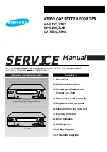
SV-610X
Brand: Samsung Pages: 3

AG513E - COMBINATION VCR/TV
Brand: Panasonic Pages: 40

DV-S103A Series
Brand: DAEWOO ELECTRONICS Pages: 53

DV-F202 Series
Brand: DAEWOO ELECTRONICS Pages: 65

VR401BMG
Brand: Magnavox Pages: 2

SVO-9600
Brand: Sony Pages: 7

SLV-SE35EG
Brand: Sony Pages: 72

SLV-SE10EE
Brand: Sony Pages: 56

13TVCR MKIII
Brand: Symphonic Pages: 23

VRZ364AT
Brand: Philips Pages: 2

VRX363AT
Brand: Philips Pages: 2

DDV9485
Brand: GoVideo Pages: 2


