4. Model WA-2700 & WA-1700 are designed with a reversible side
cover plate for the by-pass openings. Select the side to be used and
insert one of the metal collars into opening and secure by bending
tabs down. Side cover plates are installed in opposite opening.
5. Insert two (2) top mounting screws and hang main body of
humidifier on plenum. -- DO NOT TIGHTEN.
6. Sighting along a level line, select a location for the connecting
collar. Using the collar as a template, scribe a circle. Check
diameter before cutting. (7” for Model WA-2700 and 6” for Model
WA-1700.) Use same cutting procedure. Insert collar and secure by
bending down tabs.
7. Make by-pass connection using necessary pipe and elbows or
flexible duct. Insert two (2) bottom mounting screws. Tighten all four
(4) screws.
WATER SUPPLY
8. Select nearest water pipe. Mount saddle valve as illustrated in
drawing (See Figure 4.) Two (2) brass ferrules and two (2) ¼”
compression nuts are furnished to complete the connections at the
saddle valve and the unit. The installer will furnish the necessary
length of ¼” water inlet tubing.
INTRODUCTION
• LOBB Power Humidifiers are the most versatile, “common sense”
designed humidifiers on the market today. They offer you, the
homeowner, the most trouble-free, high capacity power humidifiers
yet built. Based on the proven high efficiency of the rotating drum
principle, these units deliver controlled pure water vapor into the
home up to 18 gallons per day.
•
OPERATING PRINCIPLE:
Evaporation takes place as the heated
air from your furnace passes through the moisture laden evaporative
pad. This pad, is wetted as it slowly rotates in a float controlled level
of water. The moistened warm air is then passed on into the duct
system.
• The operating principle is exactly the same on all LOBB Power
Humidifier models. Your LOBB Humidifier housing is manufactured
of the highest quality non-corrosive, easily cleaned fiberglass. All
component parts, except pad and pan liner are warranted for two
years.
• Given the necessary maintenance, your LOBB Humidifier will
provide many years of trouble-free performance and the comfort of
adequate and controlled indoor relative humidity. Carefully read the
instructions enclosed in the Homeowners Manual on caring for your
new LOBB Power Humidifier.
INSTALLATION INSTRUCTIONS
FOR MODELS WA-2700 & WA-1700
POWER HUMIDIFIERS
1. Both Models WA-2700 and WA-1700 are designed to allow
mounting on either the warm air plenum of the return air plenum.
Select a location on either plenum that will allow easy access for
cleaning and servicing. NOTE: When a cooling coil for central air
conditioning is involved, caution should be taken to insure “tapping
in” where there is any restriction of air-flow to the humidifier. (See
Figure 1.)
IMPORTANT: It is the responsibility of the INSTALLER to insure that
the installation is made in accordance with local codes, and in a
manner that does not conflict with warranties on other equipment.
PROPER APPLICATIONS OF
MODEL WA-2700 & WA-1700
2. When mounting position has been located on the plenum, scribe a
level line 12” up from the top of the furnace. Place edge of the
pressure sensitive template on the scribed line and smooth out.
3. Center punch the four (4) holes as indicated for model being
installed, and drill 1/8” holes. Using a heavy screw driver or chisel
and hammer, slash starting hole in the center of cutting line on
template. Insert shears and cut to line and follow outline for opening.
Remove remainder of template. (See Figure 2.)
2.
5.
6.
3.
4.
9. Insert the rotating drum. The LOBB WA-2700 and WA-1700
Humidifiers are designed to insert or remove the drum from either
top or bottom of unit.
10. A. Attach water pan on WA-2700 with stainless steel pan clips.
Clips are applied with dimpled side up into molded slot and locked in
position by sliding ¼” toward back of unit.
10. B. Attach water pan on WA-1700 by inserting pan so that molded
lips on rear of pan lock into rear bar on case – secure by use of brass
holding screw in front.
11.
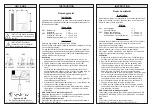
Water Level Adjustment- If necessary
With pan in place, open water supply saddle valve. To adjust water
level, loosen turn thumb screw and adjust float arm up or down.
Move float arm up to increase water level, or move it down to lower
the water level. Tighten thumb screw after adjustment. Water level
should be approximately ½” below the upper edge of the pan liner.
Do Not Overtighten Thumb Screw!
WIRING – 24 VOLT
1. All wiring must comply with local codes and ordinances. See
diagrams below. (Other optional diagrams are shown in humidistat
instructions.)
NOTE: Necessary low voltage wire to be provided by installer.
NOTE: Air flow switch can be located ahead of transformer when
electronic air cleaner is also to be controlled.
2. Set furnace controls so that fan is running. Turn humidistat to “ON”
– Humidifier should run. Set furnace controls so that fan stops –
Humidifier should stop.
3. Set furnace controls and humidistat to desired condition (35% is
recommended). The humidifier will operate automatically.
FIG. A.
Typical wiring
diagram for system with
single
speed
blower
motor.
FIG. B.
Typical wiring
diagram for systems with
multi-speed blower or
when power source is
external
to
furnace
system.
Power Humidifiers
Installation and
Operation Instructions
723 S. Route 31 • West Dundee, IL 60118
(248)623-0222
Fax (248)623-0445
Website • www.lobbair.com
WA-2700
Plenum Type
WA-1700
Plenum Type
®
P/N 522-1
Thumb
Screw
Float
Arm
Water
Float
Water
Inlet Line
Pan
Liner
Figure 5