Quick Start Guide
UMX4x4-Pro2
Further information
The document is valid with the following firmware version: 2.0.3
The User’s manual of this appliance is available on
www.lightware.eu
.
See the
Downloads
section on the website of the product.
Contact us
+36 1 255 3800
+36 1 255 3810
Lightware Visual Engineering LLC.
Peterdy 15, Budapest H-1071, Hungary
Doc. ver.: 1.0
19200032
Important safety instructions
Please read and keep the information in the attached safety instructions supplied with the
product before starting using the device.
Introduction
Lightware’s UMX4x4-Pro2, the all-round universal matrix switcher with four inputs and four
outputs, is the perfect solution for ever-changing environments such as small board rooms
and classrooms. UMX (Universal MatriX) technology was developed by Lightware to support
various analog and digital audio visual formats. VGA, YUV, digital DVI, HDMI with HDCP,
stereo analog, and S/PDIF digital audio signals are all supported.
Box contents
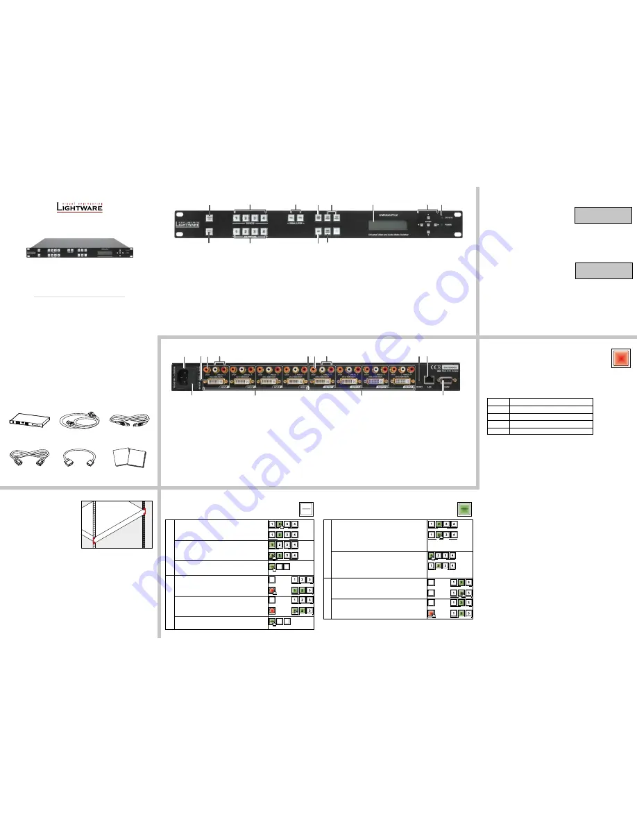
Switching operations
1. First, press and release the desired
source button
.
The pressed source button and all destination buttons
which are currently connected to the source lights up.
SOURCES
DESTINATIONS
2. Press and release the desired
destination buttons
which have to be (dis)connected to/from the selected
source. The preselected destination buttons will blink.
SOURCES
DESTINATIONS
3. Press and release
Take
button; the selected input is
switched to the selected output(s).
Lock an output
1. Press and release the
Output Lock
button; it starts to
blink and all the buttons of any locked destinations light
up (view state).
OUTPUT
LOCK
CONTROL
LOCK
SOURCES
DESTINATIONS
2. Press and release a
destination button
; it starts to
blink (more destinations can be selected sequentially).
OUTPUT
LOCK
CONTROL
LOCK
SOURCES
DESTINATIONS
3. Press and release the
Take
button. The selected
destinations are now locked.
Front panel controls in TAKE mode
Take
mode allows the user to connect or disconnect multiple outputs to an input
at once. This mode is useful when the time delay is not allowed between multiple
switching. The commands are only realized when the
Take
button is pressed.
LOAD
PRESET
SAVE
PRESET
TAKE
AUTO
LOAD
PRESET
SAVE
PRESET
TAKE
AUTO
Switching operations
1. Press and release the desired
destination
button
.
The pressed destination button and the actually
connected source button light up green. If no source is
connected (the output is muted) no source button will
light up.
SOURCES
DESTINATIONS
2. Press and release the desired
source button
. The
switch action will be executed immediately. Switching
between sources to the selected destination can be done
directly.
SOURCES
DESTINATIONS
Lock an output
1. Press and release the required
destination button
.
Now the selected destination button and the currently
configured source button light up (view mode).
OUTPUT
LOCK
CONTROL
LOCK
SOURCES
DESTINATIONS
2. Press and release the
Output Lock
button; it lights up
in red, and lock function is activated at once. No source
can be changed at the locked destination.
OUTPUT
LOCK
CONTROL
LOCK
SOURCES
DESTINATIONS
Front panel controls in AUTOTAKE mode
Autotake
mode is useful when immediate actions must be done or fast switching
is needed between sources on a particular destination. In this mode switching
occurs immediately upon pressing one of the input selector buttons.
Pay attention to the states of the Signal layer buttons which determine the layers when
executing switching or locking operations.
Mounting with front rack ears
The front rack ears allow mounting the device
as a standard rack unit installation.
Ventilation
To ensure the correct ventilation and
avoid overheating let enough free space
around the appliance. Do not cover the
appliance, let the ventilation holes free on
both sides.
The cooling of the device is ensured by convection only.
Powering on
Connect the power cord to the device’s IEC C14 standard power input connector. The router
is immediately powered ON when the power cord is connected to the AC source. The matrix
beeps two times and
Booting…
appears on the LCD screen while the initial self-test is run.
Last configuration is reloaded and the appliance is ready to use. In the case of a hardware
failure, an error message is displayed.
After switching ON, the router reloads the latest settings that were used before it was
turned off. The router has an internal emergency memory that stores all current settings and
tie configurations. This memory is independent from presets and invisible for the user. This
built-in feature helps the system to be ready immediately in the case of a power failure or
accidental power down.
UMX4x4-Pro2
matrix switcher
IEC power cable
LAN cross-link cable,
CAT5e type, 3m length
RS-232 straight
serial cable
Safety and warranty info,
Quick Start Guide
VGA to DVI-D
adapter cable (4x)
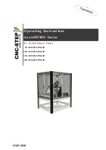
Front view
1
Control lock
Disables or enables front panel operations. Red light
means the switching and function buttons are disabled.
2
Sources
Buttons to select an input, to select a preset number or to
view the state of the selected input port.
3
Layer selection
Audio and video signals are placed on different layers so
they can be switched separately or at the same time. Layer
select buttons choose the desired signal(s) to be switched.
4
Take button
Switching between Take and Autotake working modes;
keep the button pressed for 3 seconds to toggle the modes.
5
Preset buttons
Performing preset operations (Load and Save).
6
Display
2x16 character LCD display for menu operations.
7
Menu navigation
Up, down, left, right and enter buttons.
8
Status LEDs
Power LED indicates that the unit is powered on and CPU
LIVE blinking LED indicates normal operation.
9
Output lock
Lock and protect one or more outputs.
q
Destinations
Buttons to select an output or to see the state of an output.
w
EDID button
The EDID mode can be (de)activated by the button. Use
this mode to set up the emulated EDID on the inputs, learn
EDID form the outputs, or to view the EDID memory. The
illuminated button shows that the mode is active.
e
Signal present
This Signal present mode can be (de)activaed by the
button. Use this mode to check the presence of the display
devices and incoming signals. The illuminated button
shows that the mode is active.
Rear view
1
AC connector
Standard IEC connector accepting 100-240 V, 50 or 60 Hz.
2
Fuse
Replace with F 3.15AL type only when necessary.
3
Inputs
UMX4x4-Pro2 has 4 input ports. Each port has a video, an
analog stereo audio, and a digital audio input.
4
DVI-I input
Standard 29 pole DVI-I connectors for input connections
accepting analog and digital signals.
5
S/PDIF input
RCA jack connector for S/PDIF digital audio signal.
6
Analog audio
input
Double RCA jack connector for unbalanced, analog stereo
audio input signal (left and right channels).
7
Outputs
UMX4x4-Pro2 has 4 output ports. Each port has a video,
an unbalanced analog stereo audio, and a digital audio
output.
8
DVI-D output
Standard 29 pole DVI connectors for outputs - only digital
pins are connected.
9
S/PDIF output
RCA jack connector for S/PDIF digital audio signal.
Embedded audio is still present on the DVI-D outputs.
q
Analog audio
output
Double RCA jack connector for unbalanced, analog stereo
audio output signal (left and right channels).
w
Reset button
Reboots the matrix (the same as disconnecting from the
power source and reconnecting again).
e
Ethernet port
Standard RJ45 connector. This port can be connected to a
computer directly or to LAN via switch or router.
r
RS-232 port
9 pole D-sub female connector for standard RS-232 port.
CONTROL LOCK
If the button illuminates in
red
the switching- and function buttons are disabled.
Press and hold the
Control lock
button for three seconds to toggle the state.
When the front panel buttons are locked, remote control (RS-232, USB,
Ethernet) is still available.
LCD menu - navigation
Front panel LCD has 2 lines and 16 characters in each line. The name of the menu item is
always displayed in the first line.
Signal layers
Video and audio signals are in different layers. It means video and audio signals can be
switched separately or together. At least a layer is selected all the time. Therefore, the currently
selected layer buttons are illuminated. To toggle between the layers’ on and off state press
the VIDEO and/or the AUDIO signal layer buttons. Before every operation which effects input
and output signals (e.g. switching, muting, locking, etc.) the desired layer should be selected.
(up)
toggle between menu items
(down)
toggle between menu items
(left)
move the cursor or step back to previous menu
(right)
move the cursor
ENTER
execute changes or enter a submenu
Network settings on the front panel
Setting a dynamic IP address
1.
Navigate to the
IP settings
item and press the
enter
button.
2.
Use the
up
and
down
buttons to toggle between
the
options; set to
Enabled
.
3. Press the
enter
button to save changes.
4.
Navigate to the
Save & Exit
item with the
left
and
right
buttons, then press the
enter
button.
Setting a static IP address
1. Disable the
DHCP
setting as described above.
2.
Use the
left
and
right
buttons to select the octet;
change the value by the
up
and
down
buttons.
3. To apply the settings press the
enter
button.
4.
Navigate to the
Save & Exit
item with the
left
and
right
buttons, then press the
enter
button.
New IP settings can be applied while an active connection is alive on the Ethernet port but
in this case, the active connection will be closed automatically. Establish the connection again
to reconnect the Ethernet port.
IP ADDR fixIP
192.168.000.105
IP ADDR DHCP
CONTROL
LOCK
Safety and
warranty
info
Quick
Start
Guide
TAKE
AUTO
TAKE
AUTO
1
2
5
6
8
7
9
q
3
4
w e
1
3
2
5
7
9
8
w e
r
6
q
4