


Reviews:
No comments
Related manuals for TEM-370B Series

CHROME 400 Series
Brand: S3 Graphics Pages: 67
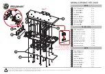
BP-VG2080RD-A2
Brand: Bitspower Pages: 5

9800PRO - 128MB Dell - Radeon AGP 8x Vga DVI Tv-out DDR X2603
Brand: ATI Technologies Pages: 64

MIC-3620
Brand: Advantech Pages: 21

6711
Brand: National Instruments Pages: 84

GS3-MT
Brand: Stanley Pages: 64

CNT24-4D(PCI)H
Brand: Contec Pages: 71

HD Video Capture Box Silver
Brand: ClearClick Pages: 12

HD Capture Box Platinum Edition
Brand: ClearClick Pages: 28

PCI-8136M
Brand: ADLINK Technology Pages: 107

HDV62A
Brand: ADLINK Technology Pages: 110

PRIMO
Brand: Trust Pages: 2

3000MP
Brand: baiMobile Pages: 33

PCI-1680U
Brand: Advantech Pages: 104

DT3010 Series
Brand: Data Translation Pages: 142

GW-DS300N
Brand: Planex Pages: 78

MBC-2690
Brand: Aaeon Pages: 18

Alveo U200
Brand: Xilinx Pages: 51


