background image

F-823-0216

02/2016

LANDOLL CORPORATION

1900 North Street

Marysville, Kansas 66508

(785) 562-5381

800-428-5655 ~ WWW.LANDOLL.COM
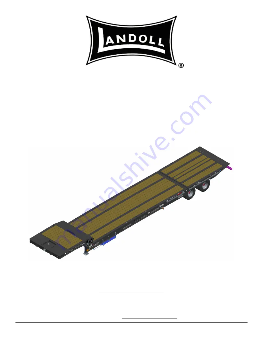
Model 900D Series

Hydraulic Tail Semitrailer

Operator’s Manual

Ea

st

ern

 W

re

cke

r Sa

le

In

c

Summary of Contents for 900D Series

Page 1: ...016 LANDOLL CORPORATION 1900 North Street Marysville Kansas 66508 785 562 5381 800 428 5655 WWW LANDOLL COM Model 900D Series Hydraulic Tail Semitrailer Operator s Manual E a s t e r n W r e c k e r S...

Page 2: ...E a s t e r n W r e c k e r S a l e s I n c...

Page 3: ...ng the Semitrailer 3 6 Parking the Trailer 3 7 Uncoupling Towing Vehicle from Semitrailer 3 7 Axle Tail Control Lever 3 8 Air Suspension Dump Valve 3 8 Loading Procedure 3 10 Securing the Load 3 12 Un...

Page 4: ...Alignment Procedure 4 15 Air Ride Suspension Axles 4 15 Brake System Maintenance 4 16 General 4 16 Spring Air Brake Chambers 4 16 Caging the Power Spring 4 16 Removal 4 17 Installation 4 17 Emergency...

Page 5: ...tring Method 4 26 Mounting Tire and Wheel 4 27 Winches 4 28 Crank Landing Gear 4 28 Repair Instructions 4 28 5 Troubleshooting Guide Electrical 5 1 Tires Wheels Suspension 5 2 Brakes 5 4 Brake Drums 5...

Page 6: ...E a s t e r n W r e c k e r S a l e s I n c...

Page 7: ...Improper maintenance will void your warranty IF YOU HAVE ANY QUESTIONS CONTACT LANDOLL CORPORATION 1900 NORTH STREET MARYSVILLE KANSAS 66508 PHONE 785 562 5381 or 800 428 5655 OR FAX 888 527 3909 CHA...

Page 8: ...read and understand the information contained in this manual and on the machine signs decals before you attempt to operate or maintain this vehicle The safety statements contained in this manual rela...

Page 9: ...ibuted GOOSENECK NON TILTING KING PIN SETTING 18 UNDERCARRIAGE TRAVEL 60 ELECTRICAL HOOKUP 7 Way Connector AIR HOOKUP Color Coded Gland Hands HYDRAULIC TAIL HYDRAULIC TAIL LOAD ANGLE 12 TAIL 15 HYDRAU...

Page 10: ...ADS 500 FT LBS SHOCK ABSORBER MOUNTING 150 FT LBS AIR SPRING MOUNTING 1 2 35 FT LBS 3 4 35 FT LBS WHEEL FASTENERS ALL MODELS OUTER SPINDLE NUTS 250 400 FT LBS PILOT WHEEL NUTS 450 500 FT LBS NOTE Capa...

Page 11: ...110 137 9 16 18 60 75 90 112 130 162 5 8 11 75 94 110 137 170 212 5 8 18 85 106 130 162 180 225 3 4 10 130 162 200 250 280 350 3 4 16 150 188 220 275 320 400 7 8 9 125 156 320 400 460 575 7 8 14 140 1...

Page 12: ...ws Use value in if using prevailing torque nuts Parker Brand Fittings Dash Size 37 Degree JIC O Ring ORS O Ring Boss ORB 4 11 13 15 17 13 15 5 14 16 21 23 6 20 22 34 36 25 29 8 43 47 58 62 40 44 10 55...

Page 13: ...ake System ABS The Anti Lock Brake System of the semitrailer is constant powered by the auxiliary blue circuit of the seven way electrical connector with backup power from the stop lamp red circuit an...

Page 14: ...0216 Edition OPERATING INSTRUCTIONS Figure 3 1 Trailer Terminology UPPER DECK LANDING GEAR CONTROL PANEL TAIL DECK LOWER DECK TOOLBOX UNDERCARRIAGE REMOTE RECEIVER E a s t e r n W r e c k e r S a l e...

Page 15: ...or down to correct height If you have the optional pin drop Jack the trailer up to take pressure off parking stand and re pin into correct height Remove jack before connecting Drain all air and moistu...

Page 16: ...rking Connecting Tractor Services to the Semitrailer 1 Connect the towing vehicle 7 pole electrical plug to the electrical receptacle on the front of the semitrailer See Figure 3 2 IMPORTANT The key o...

Page 17: ...er VIN plate located on the front of the semitrailer 5 Check tractor semitrailer rig for air leaks If air leakage is found repair the defect before transporting 6 Check the oil in each hub for proper...

Page 18: ...e warning lamp does not go off a fault exists in the semitrailer ABS Once the vehicle speed exceeds 4 mph the light should remain off unless a fault occurs or the keyswitch is turned off then on again...

Page 19: ...them to the tractor gladhand holders If present install dummy gladhands on trailer couplings 4 Disconnect the 7 pole cable and hydraulic lines from the semitrailer and store with the tractor 5 Pull th...

Page 20: ...until your travel cylinder stops dumped the air turn knob to ON c Before returning the trailer axles to transport position return the dump valve knob to the OFF position This will inflate the air susp...

Page 21: ...S 3 9 Figure 3 3 Hydraulic Controls AXLE TAIL CONTROL LEVER WINCH HYDRAULIC LEVER AIR RIDE SUSPENSION SWITCH RAMP ACTIVATION SWITCH WINCH CLUTCH CONTROL DOCK LIFT CONTROL SWITCH E a s t e r n W r e c...

Page 22: ...ing undercarriage forward to stabilize trailer for loading CAUTION WARNING 7 Winch or drive the load onto the semitrailer Insure that the load is steering straight up onto the semitrailer and does not...

Page 23: ...ING INSTRUCTIONS 3 11 Figure 3 4 Steps for Loading and Unloading TAIL TAIL DOCK LOAD POSITION TRANSPORT POSITION GROUND LOAD POSITION UNDERCARRIAGE UNDERCARRIAGE E a s t e r n W r e c k e r S a l e s...

Page 24: ...maintenance schedule is up to date and semitrailer is ready to be pulled Securing the Load WARNING 1 All items of the semitrailer load must be securely tied to the deck front and rear using the D ring...

Page 25: ...Take tension off winch cable and remove winch cable Power load off the trailer WARNING 9 If powered load is secured to both tail and lower deck attention is required before lowering tail deck Adjust l...

Page 26: ...sult if people are in the path of the rolling load 3 Failure to leave at least five winch cable wraps on the winch cable spool could allow the cable to come off the spool resulting in serious personal...

Page 27: ...b To engage the clutch winch operation Remove all air pressure 0 psi from the air fitting Free Spool Clutch Operation DP Winch DP winches are equipped with either a manual or air operated freespool cl...

Page 28: ...winch is not affected by use of the Winch Hydraulic lever ENGAGE When the handle is placed in this position the winch is engaged and cable may be spooled on or off the winch spool The winch can now be...

Page 29: ...engages dock level arm 11 Return undercarriage to transport position using Axle Tail Control Lever until hydraulic system works against the fully extended hydraulic axle cylinder 12 Shut off the hydra...

Page 30: ...Operation DOCK LEVEL ARM ENGAGING POSITION DOCK LEVEL ARM FULLY ENGAGED POSITION BEGIN OF LIFT DOCK LEVEL ARM FULLY ENGAGED POSITION FULL LIFT 30 DOCK LEVEL STOP DOCK LEVEL ARM POCKET LIFT ARM RECEIVE...

Page 31: ...mp to settle upon ramp supports See Figure 3 10 CAUTION 2 To lower ramp push ramp activation button in Hold until ramp raises off ramp supports While holding ramp palm button rotate ramp support handl...

Page 32: ...OSITION UPPER DECK RAMP RELEASING UPPER DECK RAMP LOWERED POSITION RAMP PALM BUTTON RAMP SUPPORT LATCH RAMP SUPPORT HANDLE LATCH POSITION RAMP SUPPORT LATCH RETRACTED RAMP SUPPORT HANDLE RELEASE POSIT...

Page 33: ...the ignition key to the START position The engine should crank and then start CAUTION 6 When the engine starts release the key 7 To adjust the speed turn the throttle control in or out as needed unti...

Page 34: ...F 823 0216 Edition OPERATING INSTRUCTIONS Figure 3 11 Hydraulic Engine Package Control Panel Option LANDING GEAR CONTROL ENGINE THROTTLE ENGINE IGNITION SWITCH E a s t e r n W r e c k e r S a l e s I...

Page 35: ...the bulkhead off See Figure 3 12 DANGER Figure 3 12 Bulkhead Option If suspension air loss should occur completely deflate suspension and temporarily operate on the air springs internal rubber bumper...

Page 36: ...ble 3 10 and Table 3 11 and count the number of blinks to determine the output with the fault e The transmitter s red LED blinks 1 time per second if the batteries are low and need to be replaced To c...

Page 37: ...hin 4 inches of the sides of the trailer ground clearance of no more than 22 inches placed no more than 12 inches from the rear of the trailer capable to deflect 5 inches The standard also specifies m...

Page 38: ...TIFICATION DECAL TO BE LOCATED ON FORWARD FACING SURFACE 12 INCHES FROM CURB END OF GUARD ABS LIGHT ENERGY PAK DECAL TO BE LOCATED ON REARWARD CURBSIDE OF REAR IMPACT GUARD AS SHOWN WARNING DECAL TO B...

Page 39: ...be used to power any additional electrical devices while the semitrailer is moving forward However additional devices such as remote controls may be powered from the auxiliary circuit while the semitr...

Page 40: ...5 Periodically check drain holes in the bottom of the relay valve for trailers with air brakes and storage compartments They must be open at all times to avoid moisture entrapment Hot Weather Operati...

Page 41: ...e using the tractor or trailer 2 Use Troubleshooting Guide on page 5 1 to check for SYMPTOMS and PROBLEMS of any trailer system not functioning correctly or where wear distortion or breakage is found...

Page 42: ...tion MAINTENANCE AND LUBRICATION Figure 4 1 Lubrication Points 1 of 2 1 5 6 1 6 1 3 1 3 7 5 8 5 6 592 5 1 1 3 8 2 1 1 5 1 1 5 1 6 7 52 56 06 7 86 1 6 6 867 56 175 5 6 6 67 0 E a s t e r n W r e c k e...

Page 43: ...0XP100 6 ALL YEAR Beacon EP Mobilux EP Mulitiplex Red Multifak EP Alvania EP 7 ALL YEAR Teresstic 32 DTE Light Condor 32 or Magnus 32 Regal Oil R O 32 Turbo T 32 8 ALL YEAR Gear Oil GX SAE 80W 90 Mobi...

Page 44: ...I I 2 c WARN 20K 30K PLANETARY WINCH GEAR CASE I I 3 c DP 12K 15K 20K 30K WINCH GEAR CASE I I 4 c BRADEN 12K 20K WINCH GEAR CASE I I 5 c WARN 12K PLANETARY WINCH CABLE ASSY I I L 7 c h WARN 20K 30K PL...

Page 45: ...ERVICE PRECLEANER ELEMENT X SERVICE AIR CLEANER ELEMENT X CHANGE OIL X CHECK SPARK PLUG CONDITION AND GAP X REMOVE COOLING SHROUDS AND CLEAN COOLING AREAS X CHANGE OIL FILTER X NOTES PERFORM THESE MAI...

Page 46: ...of corrosion 5 Replace any missing or illegible decals Replace any missing or damaged reflective tape 6 Use Troubleshooting Guide to check for SYMPTOMS AND PROBLEMS of any semitrailer system not func...

Page 47: ...Table 4 3 5 Use the fuel recommended for the engine package installed on your semitrailer Electrical System 1 Maintenance of the electrical system consists of inspection and minor servicing Any wire...

Page 48: ...DS24 DS25 DS26 LIGHT SWITCH 7 WAY RECEPTACLE FRONT OF TRAILER MARKER SLOPE LEFT DS5 MARKER SLOPE RIGHT DS6 MARKER LEFT TURN DS7 MARKER RIGHT TURN DS8 MARKER MID LEFT DS9 MARKER MID RIGHT DS10 MARKER...

Page 49: ...N WINCH IN OUTPUT BLUE WINCH OUT OUTPUT GREEN TAIL UP OUTPUT WHITE TAIL DOWN OUTPUT BLACK GROUND RED POWER 9 TO 30 VDC 9 TO 30 VOLT L1 WINCH OUT UP L2 WINCH IN L3 RAMP UP UP L4 DOCK ARM TAIL UP L5 TAI...

Page 50: ...E CONNECTOR DS10 MID RIGHT SIDE MARKER YELLOW J10 REMOTE RECEIVER CONNECTOR DS11 LEFT REAR SIDE MARKER RED J11 REMOTE CONNECTOR DS12 RIGHT REAR SIDE MARKER RED J12 FRONT CORNER MARKER LEFT CONNECTOR D...

Page 51: ...Block height is dependent upon suspension ride height and or axle brake size 4 Lower the trailer by exhausting air from the air springs by moving the control arm to the down position about 45 until t...

Page 52: ...m Figure 4 6 Air Ride Height Adjustment EXHAUST PORT OUT TO AIR BAGS IN FROM AIR SUPPLY TANK LOCATED ON BUMPER USED ON TRIPLE AXLE MODELS ONLY 1 4 ADJUSTING LOCK NUT LOCATING PIN ADJUSTING BLOCK SLOT...

Page 53: ...wheel bearing surfaces of the spindle being checked and the other point on the inner bearing surface on the other spindle See Figure 4 7 3 Move the axle gauge and place against the back side of the ax...

Page 54: ...ing Axle for Bend Figure 4 8 Examples of Camber GAP INDICATES BEND SET POSTION TOP OR BACK AXLE CHECK POSITION BOTTOM OR FRONT 3 POINT AXLE GAUGE POSITIVE CAMBER ROAD NO CAMBER ROAD NEGATIVE CAMBER RO...

Page 55: ...air ride suspension is aligned and adjusted at the factory and it should not be necessary to align the axles If however it does become necessary to align the axles the procedure is as follows 1 To al...

Page 56: ...lication and release Examine yoke pin for wear and replace as necessary The spring chamber should not be serviced Replace entire unit both service and spring chamber if spring chamber becomes faulty W...

Page 57: ...ten the clamp bands 3 Position the breather hole in the downward facing position by loosening the clamp bands on the spring brake chamber and rotating the chamber housing until the breather hold faces...

Page 58: ...ining wear and keep brakes adjusted Brakes should not be adjusted manually except when relining brakes Disassembly for 12 1 4 X 7 1 2 Brakes 1 Release brakes and back off slack adjuster 2 Remove slack...

Page 59: ...ift the top shoe and take out the top cam roller 6 Lift out the shoe retractor spring which is now free of tension 7 Swing the lower shoe back approximately 180o to relieve the tension on the shoe kee...

Page 60: ...LLER PIN ROLLER RETAINERROLLER PIN RETRACTOR SPRING RETAINER PQ BRAKE SHOES SHOE KEEPER SPRING ANCHOR PIN SHOE RETRACTOR SPRING BRAKE CHAMBER ANCHOR PIN BUSHINGS ABS SENSOR CAMSHAFT SEALS CAMSHAFT BUS...

Page 61: ...f 105 psi reservoir pressure must be maintained If air pressure is not available the spring brake must be manually caged 3 Remove the existing slack adjuster and clevis DO NOT REMOVE EXISTING JAM NUT...

Page 62: ...the brakes several times to check for adequate clearance to all adjacent components 6 Measure the distance from air chamber to 1 2 pin Apply brakes with 100 105 psi air pressure and remeasure distance...

Page 63: ...the brake drum It may be necessary to release the slack adjuster b Remove hub cap and catch lubricant in a pan c Remove outer spindle nut spindle locking washer inner spindle nut and bearing Remove h...

Page 64: ...emove the hub support allowing the hub to rest on the bearings n Install and adjust bearings See Wheel Bearing Lubrication and Adjustment on page 4 25 o Install the hub cap with the proper gasket Tigh...

Page 65: ...he lock washer and the washer tang fits in the spindle keyway 10 Install the outer lock nut and tighten to 250 300 ft lbs End play of 001 to 010 must be present in the adjusted wheel bearing assembly...

Page 66: ...Method Measure around each tire on the tread surface A maximum difference of 3 4 is allowed between the two mating tires of a dual See Figure 4 17 Figure 4 17 Measuring Tape Method Straight Edge or St...

Page 67: ...uter tire are accessible 4 Install the flange nut and tighten to 50 foot pounds using the sequence in Figure 4 19 Then tighten to full torque of 450 to 500 foot pounds 5 Torque will drop after the fir...

Page 68: ...cone sealant must be used Dow Corning 700 or equal is recommended 3 Remove grease before disassembly Drive spiral pins from output spur gear and input gear 4 Then drive out output shaft by placing a p...

Page 69: ...ON SHAFT 1 SPEED ROLL PIN THRUST BEARING COLLAR INNER LEG ASSEMBLY STD SHOE SHOE AXLE OUTPUT SHAFT SPIRAL PIN INPUT SPUR GEAR BUSHING SHIFT HOUSING SHIFT HOUSING BOLT GREASE SEAL STD CRANK W HARDWARE...

Page 70: ...4 30 F 823 0216 Edition MAINTENANCE AND LUBRICATION Table provided for general use NOTES E a s t e r n W r e c k e r S a l e s I n c...

Page 71: ...d wire loose Clean and tighten ground LIGHTS FLICKERING Wires shorted or loose Locate insulate replace or tighten Grounding through fifth wheel Locate broken ground wire tractor or semitrailer LIGHTS...

Page 72: ...EAR Over inflation Deflate to correct inflation See Tire Inflation on page 4 25 SHOULDER TREAD WEAR BOTH SHOULDERS Under inflation Increase inflation to correct PSI Check axle alignment See Tire Infla...

Page 73: ...gnment Re align axle See Axle Alignment on page 4 15 TRACKS TO EITHER SIDE Broken or bent springs or equalizers Replace defective parts Axles not parallel Re align axles AIR RIDE HEIGHT PROBLEMS TOO H...

Page 74: ...4 2 Worn brake shoe bushing Replace bushing Brake drum distortion Replace drum Broken brake chamber spring Replace spring Brake chamber pushrod binding Re align brake chamber bracket Air brake line l...

Page 75: ...BRAKES RELEASED Relay emergency valve leaking Repair or replace valve Leaking tubing or hose Replace defective part EXCESSIVE LEAKAGE WITH BRAKES APPLIED Relay emergency valve leaking Repair or replac...

Page 76: ...ting conditions or loads that create severe or excessive brake applications BRAKES PULL TO EITHER SIDE Drums of different diameters Replace with drums of same diameter Foreign matter in drums Clean dr...

Page 77: ...eck all components and relief valve for proper settings Excessive load Check unit specifications for load limit See Standard Specifications on page 2 1 Slipping or broken pump drive Repair or replace...

Page 78: ...2 5 to 3 1 GPM flow FOAMING OF OIL Incorrect low or dirty oil Replace clean or add oil as needed Water in oil Replace oil Air leaks Check suction line and component seals for suction leaks Replace de...

Page 79: ...IN FUNCTIONS DO NOT WORK Check the wiring connection from the system to the valve coil for the output function that does not work Tighten loose connections Check LED status display for possible fault...

Page 80: ...5 10 F 823 0216 Edition TROUBLESHOOTING GUIDE Page Intentionally Blank E a s t e r n W r e c k e r S a l e s I n c...

Page 81: ...E a s t e r n W r e c k e r S a l e s I n c...

Page 82: ...Tail Semitrailer Operator s Manual Re Order Part Number F 823 0216 LANDOLL CORPORATION 1900 North Street Marysville Kansas 66508 785 562 5381 800 428 5655 WWW LANDOLL COM F 823 0216 02 2016 Copyright...

Reviews: