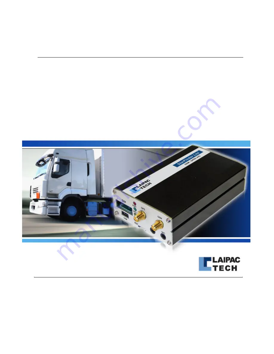
background image


StarFinder Lite  

User’s Manual & Reference Guide 

Revision 1.2 – 2012 


©1999-2008 by Laipac Technology, Inc. All rights reserved – The Specifications and information regarding the products in this manual are subjected to change without 

notice. All statements, information, and recommendations in this manual are believed to be accurate but are represented without warranty of any kind, express or implied, 

users must take full responsibility for their applications of any Products - Reproduction of the contents of this manual, in whole or in part, without written permission of 

Laipac Technology, Inc. is prohibited. 


Summary of Contents for StarFinder Lite

Page 1: ...subjected to change without notice All statements information and recommendations in this manual are believed to be accurate but are represented without warranty of any kind express or implied users must take full responsibility for their applications of any Products Reproduction of the contents of this manual in whole or in part without written permission of Laipac Technology Inc is prohibited ...

Page 2: ...xposure Statement FCC RF Radiation Exposure Statement 1 This Transmitter must not be co located or operating in conjunction with any other antenna or transmitter 2 This equipment complies with FCC RF radiation exposure limits set forth for an uncontrolled environment 3 This equipment should be installed and operated with a minimum distance of 20 centimetres between the radiator and your body CE Ma...

Page 3: ...y conformance Specific details about compliance to the following standards and regulatory bodies may be obtained from Laipac Technology Inc PCS Type Certification Review Board PTCRB Based on Cellular Telecommunications and Internet Association CTIA Over the Air OTA performance tests EN 301 511 EN 300 440 EN 62311 EN 301 489 1 3 7 and 60950 1 testing ...

Page 4: ...tware 8 3 3 2 Installation of utility software 8 3 3 3 Installation of USB driver 8 3 4 Configuration of StarFinder Lite 10 3 4 1 Start configuration of your device 10 3 4 2 Basic Configuration 10 3 4 3 Save setting into or read setting from the device 14 3 4 4 Acquire setting from or save setting into a configuration file 15 4 ADVANCED CONFIGURATION AND FEATURES 20 4 1 Setup Settings 19 4 2 Syste...

Page 5: ... Installation 36 5 2 1 Required Hardware 36 5 2 2 Installing your Starfinder Lite 36 5 2 3 Considerations 36 5 2 4 Other Options 36 5 2 5 Power Connector 37 5 2 6 Buttons Input Output 37 5 2 7 Analog Input 38 5 2 8 Optically Isolated Inouts 38 5 2 9 Three Relay Output 39 6 OPERATION 40 6 1 LED Operation 40 6 2 Position Reporting by Event 40 6 3 Position Reporting by Request 41 6 4 Serial Port 41 6...

Page 6: ...g positions for local or remote downloading The Starfinder Lite comes standard with two optical inputs for connecting to alarm systems or other sensors one analog inputs and three output relays for ignition disabling and remote door unlocking A backup battery is also included Each Starfinder Lite can be programmed with a unique device ID and can send data to any static or dynamic IP address or SMS...

Page 7: ...cessing control option Operation Temperature 30C to 65C USB Port for configuration Compatible with Mobile Data Terminal 2 Optically Isolated digital inputs 3 Outputs with relays 1 Analog input available Multiple Geo Fence capability with in out fence alert Data logger capability built in with 2500 positions memory to record time stamp speed location and event state 3 Axial motion G Sensor to repor...

Page 8: ...n your evaluation you will need the following Starfinder Lite Power and I O harness cables complete with Voice and Panic buttons GSM patch antenna 3 meters cable length GPS magnet mount antenna 5 meters cable length GPRS data enabled SIM card with known APN settings 2G and TDMA compliant Your Identity Leaflet provided in the Evaluation Kit 9 36V DC power supply USB A to USB Mini B cable PC with Wi...

Page 9: ...he valid SIM card into the SIM Card Tray on the front of the unit 4 Power on Starfinder Lite with DC power supply 12V 5 Connect the Starfinder Lite to the computer and reset the unit with reset button 6 Install USB driver on computer 7 Run utility and reset unit with reset button 8 If unit is not activated locked activate unlock it 9 If the existing firmware does not meet the request of utility up...

Page 10: ...ing 3 documents which will be great helpful for user to know about how to set up and use SF Lite quickly Utility and Firmware Release Note such as Release Note BE RN V1 34 Quick Start manual such as Quick Start Manual BE V2 0 Firmware Update Manual such as Firmware Update Manual BE V2 0 It is strongly recommended that user should go through Utility and Firmware Release Note first before he updates...

Page 11: ... You can locate the Device ID on your Identity Leaflet or more accurately in your user account on the website www LocationNow com Password Used to protect the StarFinder Lite from other people affecting its operation with SMS commands You can locate the Password on your Identity Leaflet GSM Band This is for setting a frequency that your GSM provider network operates at The North American network b...

Page 12: ...MS device Wireless Voice Plan This section initializes the voice option in the StarFinder Lite Voice Originally this setting is designed to tell unit if the existing SIM card is with voice calling enabled Currently unit has enabled this setting actively Of course if you are using SIM card without Voice Plan no calling or voice communication can be accomplished Incoming Call This setting determines...

Page 13: ...he unit to access your carrier s Access Point GPRS APN The Access Point Name is used by your SIM card to connect to the GPRS network The Access Point is the carrier s server through which the traffic becomes converted from GSM to GPRS Internet traffic Check with your SIM Card provider for this item User Name The user name authorises your SIM card to access your carrier s Access Point It could be b...

Page 14: ...d Domain Name 2a with Static IP address Warning If unit has a Fall Back Mode setting along with Primary Server and Alternative Server when it loses its GPRS connectivity with its remote servers both Primary and Alternative Server unit will initiate its action of Fall Back Mode Refer to introduction to Fall Back Mode ALTERNATIVE SERVER Configuration of the Alternative Server is optional Alternative...

Page 15: ...stem Report Fig 3 4 2 d Report and its setting This option allows you to specify how frequent the unit will send a position update You can specify the report by time value in hours minutes and seconds Also user can specify the report by distance value in kilometres miles or yards 3 4 3 Save setting into or read setting from the device ...

Page 16: ...nit Insert a valid SIM card into unit and power up the unit with DC power supply 12V Reset unit with reset button to start running application Read the setting from units By clicking Read Setting from Device button user can read the reside configuration from the unit which being connected to the running utility If unit has never been configured and valid its configuration this reading configuratio...

Page 17: ...ng files to select a prefer one such as configuration 1 then click OK If reading file is successful user can see a pop up window with prompt Success Save a set of configuration into a configuration file User can save the current edited configuration into to a configuration file follow the steps below c Click FILE Save see Fig 3 4 4c and Fig 3 4 4d Fig 3 4 4c ...

Page 18: ...ipac Technology Inc All Rights Reserved Page 18 Fig 3 4 4d User should type in the name of this new configuration file such as configuration 3 then click OK If saving operation is successful a pop up window will appear with prompt Write Config File is created see Fig 3 4 4e Fig 3 4 4e ...

Page 19: ...ICATION Among them SYSTEM settings are concerned with reporting and voice setup I O settings are used for customizable I O functionality The APPLICATION settings are used for other types of event messages 4 1 Setup Setting SETUP NEMA NMEA Baud NOT IMPLEMENTED WAAS EGNOS This setting enables the compatibility for Wide Area Augmentation System and European Geostationary Navigation Overlay Service fo...

Page 20: ...rt This is a user defined value used for report bursting and is governed by report by time An example is if the number of waypoints per report is set to 5 and the report by time interval is set to 1 minute in 5 minutes the receiving server will receive 5 waypoints Smart Log Report The smart log report option allows the unit to automatically log its position and alert information into internal memo...

Page 21: ...rt messages in the unit s internal memory By Time Interval Logs messages into internal memory based on the specified time interval By Distance Interval Logs messages into internal memory based on the specified distance interval Memory Full Alert Data Logger Memory Full alert will cause the unit to send an alert when the internal memory of the unit is full This means that once the unit runs out of ...

Page 22: ...ce with this No under conditions below a User presses the Panic button on 10 pin I O cable or b Unit is triggered by Towing Alert or Accident Alert c Emergency No 1 sending function related to these alerts are enabled SMS Base Station The SMS Base Station Number is used when the Starfinder Lite is operating under SMS mode All of the waypoints and alert messages will be sent to the SMS Base Station...

Page 23: ...uery Used as a GSM keep alive and tests the connection status of the Starfinder Lite This setting must be enabled first Query Interval The actual interval in which the Starfinder Lite tests the connection between the GPRS server and itself If there is no server response to the message the Starfinder Lite sends out the unit will reset and try to resynchronize ...

Page 24: ...Zone Use this to select your time zone so that the device knows your local time Daylight Savings Time Use this to enable the daylight savings time start and end dates DST Start Date This is a user defined value of when the user starts their daylight savings time DST End Date This is a user defined value of when the user ends their daylight savings time ...

Page 25: ... to a Low or from a Low to a High This setting is user defined Counter setting This option allows the user to implement input 2 as a counter The counting signal can be specified as either a Low to High Low High or a High to Low High Low voltage level change The maximum counting speed is 50 times per second with minimum voltage change of last at least 10 ms Counter Start Value This option allows th...

Page 26: ...oltage is Logic High 3 When engine shuts down its input voltage is back to Logic Low For definition of Logic level as its correspondent electrical characteristics refer to section 5 2 8 I O Output Output setting items allow user to activate and select the functionality related to output All three outputs are driven by individual internal relays and are wired as Normally Open For the electrical cha...

Page 27: ...e different mode user should check SF Lite Application Firmware Release Note to know about what kind of output control mode is being used by the application firmware he selects I O Buttons Panic Button Allows user to activate the functionality of the panic button by enabling it Once enabled after pressing panic button unit will initiate the actions below sequentially Send a panic alert message thr...

Page 28: ... the phone call Note For unit with application firmware V1 32 EC and V1 34 automatically both of these 2 buttons have been enabled by unit User can skip this setting I O Analog In Analog Input The Analog Input functionality must be enabled before using It is designed to detect and record input voltage range between 0 00 and 3 30 volts This voltage value will be sent to remote server in the term of...

Page 29: ...Laipac Technology Inc StarFinder Lite User s Manual Reference Guide 2012 2021 by Laipac Technology Inc All Rights Reserved Page 29 I O Com RS232 COM PORT TO BE DEFINED LATER ...

Page 30: ... Mileage Starting Value and the unit of distance during unit moves Whenever moving distance is increased by 1 km mile the incremented value will be added to the Accumulator s current mileage value Starting Value The Mileage Start Value is user defined and is recommended to match the odometer reading in the equipped vehicle From there you can specify the unit of distance being kilometers or miles a...

Page 31: ...es a movement that generates 2G or greater force the unit will send an alert to the remote server This may be in a situation where someone tows a vehicle without consent Trigger Value The G Sensor Trigger Value has a default value of 2Gs and should be kept at a low recommended value to sense movement Accident Alert The accident alert requires enabling before it is used It is designed to sense a hi...

Page 32: ...and microphone jacks 2 female SMA connectors for the GPS and GSM antennas and three LEDs to show the status of reporting and connectivity as shown in the below image The connections available on the back of the unit include two optically isolated inputs and three Relay outputs in the main I O section labeled as 12V one analog input and the TTL I O ports used for the call answer button labeled as 3...

Page 33: ...city accuracy 0 1 m s Time accuracy 1 uS Cold start acquisition time 42 Seconds Warm start acquisition time 38 Seconds Hot start acquisition time 1 Seconds Maximum velocity tracked 515 m s Maximum altitude tracked 18 000 Meters Jerk 20 m s3 Tracking Sensitivity 159 dBm Navigation Sensitivity 159 dBm 5 1 2 GSM Modem Specifications Quad band GSM GPRS component 850 900 1800 1900 MHz Designed for M2M ...

Page 34: ...2 3 MHz VSWR 2 0 Max Bandwidth 10 MHz Min Axial Ratio 3dB Typical Impedance 50 Ohm Peak Gain 4 dBic Min Gain Coverage 4dBic at 90 0 90 over 75 volume Polarization RHCP DC Voltage 3 3V 5 1 4 GSM Antenna Specifications Bands 850 900 1800 1900 MHz Frequency Range 824 960 MHz 1710 1990 MHz Impedance 50 Ohm VSWR 2 0 Gain 2dBi Radiation Omni Polarization Vertical Wave Half Wave Dipole ...

Page 35: ...ake sure the supplied fuse is in place 5 2 3 Considerations There are a few considerations you should make when installing your Starfinder Lite You should make sure the unit is somewhat accessible so that you can connect the unit to a laptop via USB for configuration and local NMEA 0183 output The GSM antenna may be mounted almost anywhere as the GSM signal is generally very strong The GPS antenna...

Page 36: ...o provide more current 5 2 6 Buttons Input Output These four connections are used by the StarFinder Lite Button Analog cable set If you are using these without the standard cable set the following summarizes the use of these connections Input BIO1 Active LOW will start answer or end a phone call if enabled Input BIO2 Active LOW will send a Panic report to LocationNow if enabled Output BIO3 Normall...

Page 37: ...Finder Lite Analog GND This is the ground reference for the Analog Input signal 5 2 8 Optically Isolated Inputs The positive wires are the sensing wires or wires that detect the voltage changes and the negative wires are for common ground The positive wires are most commonly connected to solenoid wires that drive ignition horn air conditioning gas cap door open closed status etc When the inputs ar...

Page 38: ...n be remotely controlled by the control center All three outputs have the same electrical characteristics and behavioral options The outputs serve as a switch either to drive an external relay or to open close an existing low amperage circuit Follow the electrical characteristics chart below or damage may be incurred to both unit and vehicle Also review page 30 for the output behavior Electrical C...

Page 39: ...xerted on Input 1 port will send a position message to the control center with the corresponding event code Input 2 Opto 2 An electrical current signal exerted on Input 2 will send a position message to the control center with the corresponding event code Geo Fence Once the hardware Geo Fence is set the Starfinder will report back to the control center when the unit has travelled in out the bounda...

Page 40: ... distance intervals are set they work dynamically together like an OR operation This means that whenever either condition is met it will report For detail above refer to section 4 6 3 Reporting by Request In addition to automatically reporting the position you can manually request the current position or settings The following are some parameters which can be requested System information such as f...

Page 41: ...Time Zone No No Yes GPRS Mode No Yes Yes SMS Mode No Yes Yes Voice No No Yes Incoming call No No Yes GPRS to SMS fall back No No Yes APN No Yes Yes APN username No Yes Yes APN Password No Yes Yes Domain name 1a No Yes Yes Port 1a No Yes Yes Static IP 1 No No Yes Port 1 No No Yes Domain name 2a No No Yes Port 2a No No Yes Static IP 2 No No Yes Port 2 No No Yes DNS IP 1 No Yes Yes DNS IP 2 No Yes Ye...

Page 42: ... Starter Control on off No No Yes Timer Control 1 Value No No Yes Output 2 as No No Yes Horn Control on off No No Yes Timer Control 2 Value No No Yes Output 3 as No No Yes Siren Control on off No No Yes Timer Control 3 Value No No Yes Panic Button No No Yes Panic Alert with Following Action No No Yes Call Button No No Yes Call Function No No Yes Analog Input No No Yes Alert when Analog Input Reach...

Page 43: ...y Inc All Rights Reserved Page 43 Geo fence Setup Yes Yes No Switch Relay 1 Yes Yes No Switch Relay 2 Yes Yes No Switch Relay 3 Yes Yes No Request Real Time Position Yes Yes No Request Device Data Yes Yes No Request Current Status Yes Yes No Disable G sensor Yes Yes No Disable Geo fence Yes Yes No ...

Reviews: