KVM-TEC Smartline SVX Series, Manual
The KVM-TEC Smartline SVX Series is a high-performance product designed to optimize your work environment. Access the user manual for this cutting-edge product for free on our website. Take advantage of its advanced features and enhance your productivity today. Download the user manual at manualshive.com.
Share
Download


Reviews:
No comments
Related manuals for Smartline SVX Series
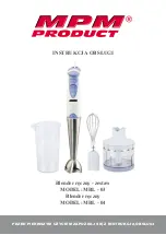
MBL-03
Brand: MPM Pages: 24

6200-FX
Brand: Accelerated Pages: 16

cook&seat KP-508WGH
Brand: ICA Pages: 24

BS4717 Ruby Red
Brand: UFESA Pages: 36

NA-EX01R
Brand: J-Tech Digital Pages: 12

T12019
Brand: Tower Hobbies Pages: 16

ST121HDT4P
Brand: StarTech.com Pages: 10

DC-LINK-ULR1
Brand: DwarfConnection Pages: 2

BHM350BM
Brand: Mirta Pages: 48

ZHB4571 SANO
Brand: Zelmer Pages: 64

EXT-DP12-OPT
Brand: Analog way Pages: 2

MultiQuick 5 MQ 523 Baby
Brand: Braun Pages: 24

TriFlex SC-TriH/O-72-OD-Kit
Brand: SureCall Pages: 20

Pronto RFX9600
Brand: Philips Pages: 2

SWV 733 B2
Brand: Silvercrest Pages: 12

SWV 733 B1
Brand: Silvercrest Pages: 152

SWV 733 A2
Brand: Silvercrest Pages: 164

SWV 300 C1
Brand: Silvercrest Pages: 312


