KOHJINSHA KA1 Series, Instruction Manual
The KOHJINSHA KA1 Series Instruction Manual is a valuable resource for users of this innovative product. Available for free download at manualshive.com, this comprehensive manual provides essential guidance and information, allowing users to maximize their KA1 Series experience. Get your free manual now and unlock the full potential of your device.
Share
Download


Reviews:
No comments
Related manuals for KA1 Series

ANT 033
Brand: Williams Sound Pages: 4
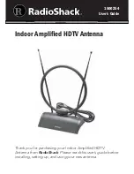
1500254
Brand: Radio Shack Pages: 8

AD5900-27
Brand: Trango Systems Pages: 2

18T Series
Brand: Andrew Pages: 2

AAN X1
Brand: AEG Pages: 10

YX500-PCS
Brand: Wireless Extenders Pages: 19

GEOSATpro GS120 DiSEqC
Brand: Satellite AV Pages: 10

BGAN Remote Antenna
Brand: Hughes Pages: 10

WAYFARER 1.2M KA-BAND
Brand: Norsat Pages: 29

WAYFARER 1.0M KU-BAND
Brand: Norsat Pages: 32

MG-4000VHQ
Brand: Sqish Pages: 18

AU-3C-GSM
Brand: Etek Navigation Pages: 5

CUE DEE 5861
Brand: etech components Pages: 6

FM Coupler
Brand: XM Radio Pages: 12

20M5-125
Brand: M2 Antenna Systems Pages: 10

AK-26G
Brand: A.H. Systems Pages: 10

SAS-562B
Brand: A.H. Systems Pages: 15

2MCP22
Brand: M2 Antenna Systems Pages: 7


