CCE-3000 Series
1
Installation Guide
Installation Guide
Pneumatic-Electric Relays, Single and Multi-Stage
CCE-3000 Series
Mounting
The CCE-3000 Series relays are
not
position sensitive
and may be mounted in any orientation.
Model CCE-3001
1. Surface mount using the two 3/16" diameter
holes.
2. Bulkhead mount using the 9/16-18 boss and nut.
Model CCE-3002/3003
1. Surface mount using the two 3/16" diameter
holes.
2. Bulkhead mount using two #6 self-threading
screws.
Mounting
1
Model CCE-3001
1
Model CCE-3002/3003 1
Connections and Wiring 1
Electrical
1
Air Supply
1
Adjustments and Calibration 2
Accessories
2
Maintenance
2
Specifications 2
Important Notices 2
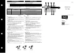
CCE-3001
CCE-3003
Connections and Wiring
Electrical
Connections are made to 1/4" quick connect ter-
minals. Do not exceed the electrical ratings of the
switches (see
Specifications on page 2
).
1. Connect to the Common “C” and Normally Open
“NO” terminals if a fall in signal should break the
circuit.
2. Connect to the Common “C” and Normally
Closed “NC” terminal if a fall in signal should
make a circuit.
Air Supply
1. Using 1/4" (6 mm) OD polyethylene tubing,
connect the signal to the 3/16" (5 mm) inlet in the
bottom of the unit.
2. Limit the signal to 30 psig (207 kPa) max.
CAUTION
Pneumatic devices must be supplied with clean, dry
control air. Any other medium (e.g., oil or moisture
contamination) will cause the device to fail.