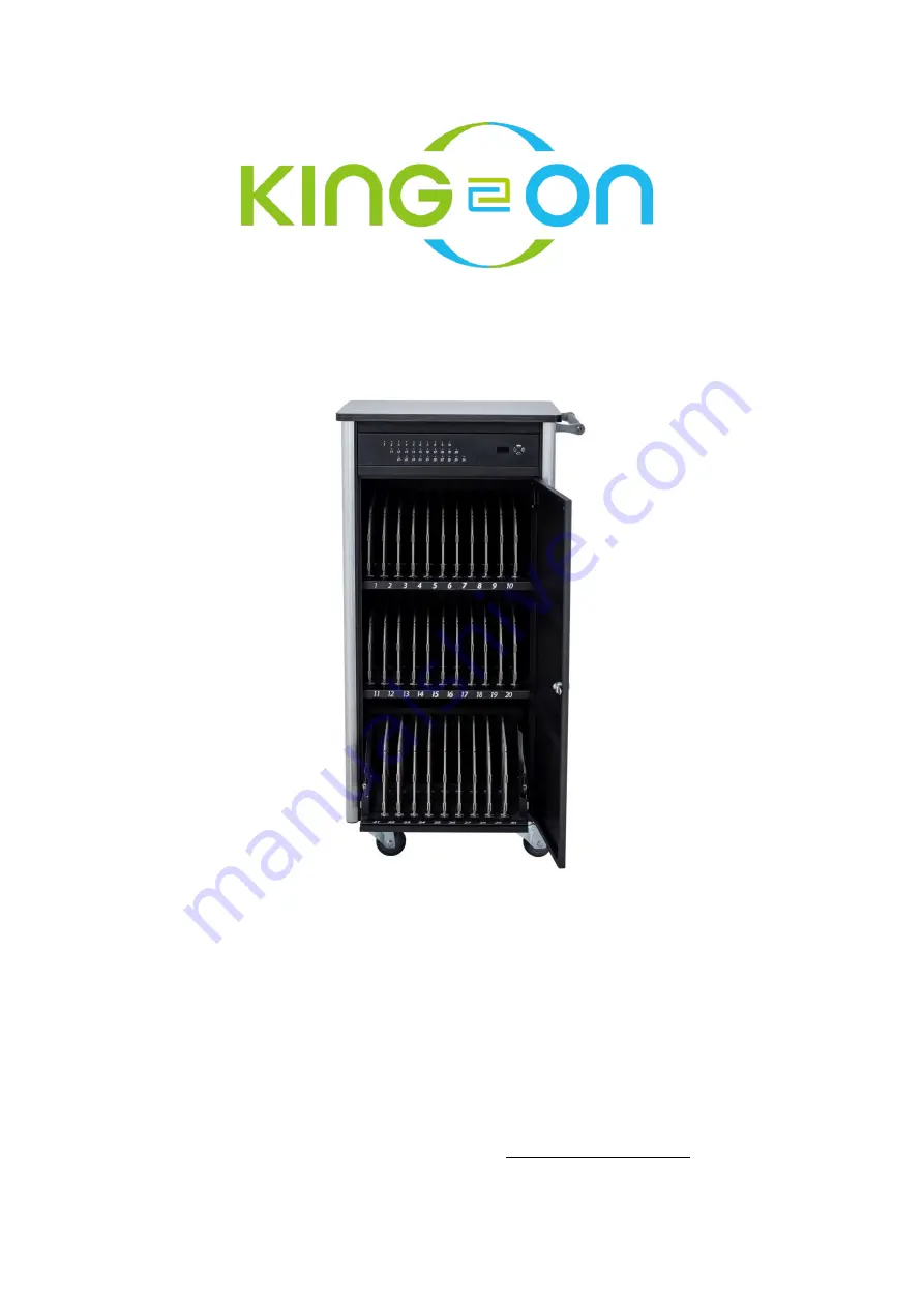
background image


  User Manual


30-Port Smart USB Type-C Charging Trolley 


V. 1.1 

Copyright©2020 KING-ON              www.king-on.com.tw   

Summary of Contents for SCMR30

Page 1: ...User Manual 30 Port Smart USB Type C Charging Trolley V 1 1 Copyright 2020 KING ON www king on com tw ...

Page 2: ...Contents ...

Page 3: ... 0 and the 30 Port Smart USB Type C Charging Trolley also provides this company s network monitoring module for charge management to simultaneously manage multiple trolleys and conveniently provide charging information The 30 Port Smart USB Type C Charging Trolley SCMR30 is easy to use Please refer to this user manual for future use If you need any further assistance please contact your local deal...

Page 4: ...roduct on a flat level surface at least two feet from any heat source such as ranges or heater Keep all liquids away from the product Cleaning Turn the product off and unplug it before cleaning Use only a dry soft cloth to wipe the outside of the product Smart Devices Please properly place your smart devices or power pack on a surface so that it will not fall or drop Plug and Socket figure 1 figur...

Page 5: ...then plug it to a power outlet The front panel and buttons of the trolley provide basic charging instructions First of all please understand that the charging mode of a smart device will start with fast charging and end with slow charging The smart device will switch between them automatically according to the battery status Correctly interpreting the information on the panel can help you understa...

Page 6: ...anel A This displays all charging ports on the Trolley device a lit indicator means a charging port is currently in use B Yellow frame 2 The image below shows the status of charging ports schedule modes and main menu ...

Page 7: ...ing Purple red base blue indicator flashing slowly The selected USB Type C port is charging without quick charge note Purple red base blue indicator flashing quickly The selected USB Type C port is quick charging note Purple indicator red base blue indicator The selected USB Type C port has completed charging Note i Charging current of less than 1A is standard charging higher than 1A is quick char...

Page 8: ...o a power outlet b Turn on the power switch c Prepare USB Type C cables to charge your devices 5 2 Connection instructions a Connect the USB Type C cable to your device b Connect the other end of the USB Type C cable to any charging port c The LED indicator corresponding to the charging port will display the current charging mode refer to 4 2 for details on LED status indicators d The display will...

Page 9: ...s the current number of devices being charged The blue frame shows the current number of devices that have completed charging the total number of devices that can be supported The red frame shows possible scheduled charging On or Off The green frame shows date and time display a 1 Simultaneously press the left and right keys to enter settings mode press the down key to enter the schedule menu pres...

Page 10: ...eft right keys to set date a 3 Continue and press the down key to enter time settings time can be set similarly to date settings Once all settings are complete press and hold the left key to exit to the save settings menu select Yes then press and hold the left key to return to the main menu ...

Page 11: ...r loading automatically If the temperatures get high system will active a fan for cooling until the power loading getting low Once the system detects that the activated fan has stopped a notice will pop up on any screen to show Fan 1 Stop Fan 2 Stop or Fan 1 2 Stop on any screen as shown in the images below The setting operation can still be used normally and will not be affected by these message ...

Page 12: ...splayed 10 seconds after startup please contact the after sales for technical support At this point the system will automatically reduce load to ensure that protective systems continue to operate users can still charge devices without impact but charge times might become longer 5 Fan1 2 Stop If Fan 1 2 Stop is displayed please restart and check the fans if Fan 1 2 Stop is still displayed 10 second...

Page 13: ...ty of current port no display unit default unit is Amperage hour Ah v TCur Total current of all charging ports Amperage is displayed as A vi Battery icon in bottom left corner Device is not connected Device is connected with standard charging Device is connected with quick charging Charging has completed for the device Next press the up down left right keys to select a port to view its charging in...

Page 14: ...i DC 5V Left image shows single port charging so Curr and TCur values are similar ii DC 9V iii DC 12V iv DC 15V ...

Page 15: ...ht key in the single port indicator menu to go to the schedule menu c2 Press and hold the left and right keys to enter schedule settings week should be highlighted c3 Use the up and down keys to highlight settings and make adjustments similarly to the methods for date and time as detailed in a 2 and a 3 ...

Page 16: ...Then press and hold the left button to finish saving and return to the main screen The minimum unit for scheduled charging is hour with a total of 3 modes as shown below 1 SCH School mode The default setting of this mode is Monday to Friday with charging activated from 8 00am 6 00pm charging is deactivated on Saturdays and Sundays Users can freely set the charging periods 2 HOD Holiday mode The de...

Page 17: ...overload protections for single port current and total output 2 Support for USB PD3 0 specification Power Input socket AC 220 240 V 50Hz 10A External output sockets x2 AC 220 240V 50Hz Maximum output 10A When the external sockets and charging devices are used at the same time the maximum total output power is 2200W 10A when the using power was over the limitation the protection switch will be acti...

Page 18: ...ames and product names used in this document are trademarks or registered trademarks of their respective holders Cable management Independent cable organization rack and fixed slot dividers Dividers Fixed slot dividers Anti theft mechanism Both front rear doors include anti theft locks Dimensions W x D x H 532 x 503 x 1112 mm including height of casters hidden handles Package dimensions W x D x H ...

Page 19: ...pment generates uses and can radiate radio frequency energy and if not installed and used in accordance with User Guide may cause harmful interference to radio communications Operation of this equipment in a residential area is likely to cause harmful interference in which case the user will be require to correct the interference at his her expense CE Statement This is a Class B product in the dom...

Reviews: