KFV Karl Fliether GmbH & Co. KG - Siemensstr. 10 - 42551 Velbert - Telephone: +49 2051/278-0 - Telefax: +49 2051/278-167
[email protected] - www.siegenia-aubi.com
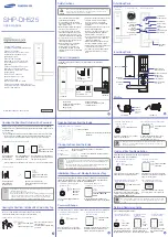
1.) Mechanical installation
Increase the GENIUS lock recess at the top near the power cable by approx. 15 mm.
Install cylinder in accordance with DIN 18252.
CAUTION: Metal filings at the connecting terminals of the GENIUS System may damage the internal electronics.
GENIUS systems with the convenience feature (CA/CB only) do not have openings for
door-handle rose bolts.
3.) Operating mode:
Switch position up = day mode
Switch position down = night mode
4.) Detection of open/closed door:
Install the sensor centrally (± 1 mm) to the reed sensor.
Max. distance 4 mm (± 3 mm)
2.) Connections GENIUS type B
Position State
Notes
The lock is fully locked and the
door is closed.
•
For use in combination with alarm systems.
› Terminal 7 is connected to negative (--) ground.
The door is closed
•
For use in combination with doorman monitoring.
› Terminal 7 is connected to negative (--) ground.
The latch is pulled into the cylin-
der operated lock
•
For use in combination with a revolving door motor.
› Terminal 7 is connected to negative (--) ground.
A connected alarm system can be
activated or deactivated
•
Control with 2-channel infra-red access key*
•
In order to keep the alarm system activated in the event of a po-
wer failure, the terminal is connected to negative/ground when
the alarm is deactivated.
› Alarm deactivated = terminal 7 = negative -- relay on
› Alarm activated = terminal 7 = high resistance -- relay off
•
The relay break contact must be used to switch on the alarm
system.
5.) Rotary switch (optional signal outputs)
Terminal 7; open collector; max. load 20 mA; isolated due to coupling relay 24V (KFV accessory).
Fig. 1
Fig. 2
Connec-
tions
Function
A, B, C, D
B, C, D, 2
Connection for the IR sensor which carries
IR signals to the GENIUS door lock switch
Connection of KFV finger scanner
0, 1
Mode switch
Day/night mode
2, 3
Operating voltage 24V DC
Terminal 2 = + positive
Terminal 3 = – negative
4
External unlocking signal.
If +24 VDC is supplied to this terminal for
≥
1 sec., then an opening cycle is perfor-
med in both operating modes
7
Lock status indication.
The desired state is selected by the
rotary switch (optional signal output max.
20mA)
* See GENIUS operating instructions for details on controls
1
2
3
4
1
2
3
4
1
2
3
4
1
2
3
4
H47.ELEKKFV0005EN/2013-08/0
For fast access
Quick Reference
GENIUS type B
EN