background image

ASL120 Series Smart Lock

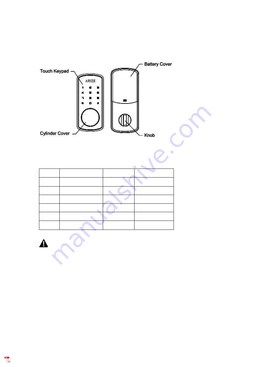
Main Parts and Diagram

Thanks for choosing our ASL120 smart lock.
Please check the user manual carefully before operation and installation.

Packing

NO

Model Type

Quantity

Note

1

Front Plate

1

2

Back Plate

1

3

Mortise lock

1

4

Battery cover

1

5

Accessories

1

6

Battery

1

4pcs / group

Warning:

Changes or modifications to this unit not expressly approved by the party responsible for compliance
could void the user’s authority to operate the equipment.

Summary of Contents for ASL120 Series

Page 1: ...e operation and installation Packing NO Model Type Quantity Note 1 Front Plate 1 2 Back Plate 1 3 Mortise lock 1 4 Battery cover 1 5 Accessories 1 6 Battery 1 4pcs group Warning Changes or modifications to this unit not expressly approved by the party responsible for compliance could void the user s authority to operate the equipment ...

Page 2: ...ide the battery cover and unscrew the 3pcs screws then take off the back plate and pad Please confirm whether to adjust the mortise lock based on the distance I from the center hole to door frame The default Backset of the mortise lock is 60mm If need to change please follow the below instruction ...

Page 3: ...de direction please adjust the latch to release with screwdriver 5 Install the front plate and back plate as the diagram the cylinder trail of the front plate need be horizontal 6 Combine the lines to the plug on the back plate then install the back plate on the back pad Please fasten the extra lines to the back pad rather than stuff the lines to the holes ...

Page 4: ... System Resetting 1 If the battery is dead you can disassemble the cylinder cover and charge it by one 9V emergency battery 2 If the system crashed you can insert one pin to the reset button to reset the system 3 If the electronic parts do not work you can open the door by the mechanical key Restore Factory Mode Setting If you forget the master code you can remove the battery cover and Insert one ...

Page 5: ...er Show the user code Step6 Enter Return to step4 Enter Continue to create user code Enter Return to the upper menu Use the User code to unlock the lock Step1 Wake up the screen touch the screen to activate Step2 Enter the user code Enter Connect to the gateway Step1 Wake up the screen touch the screen to activate Step2 Enter the master code Enter Step3 Enter key 7 Enter Step4 Enter key 1 Enter St...

Page 6: ...o communications However there is no guarantee that interference will not occur in a particular installation If this equipment does cause harmful interference to radio or television reception which can be determined by turning the equipment off and on the user is encouraged to try to correct the interference by one or more of the following measures o Reorient or relocate the receiving antenna o In...

Reviews: