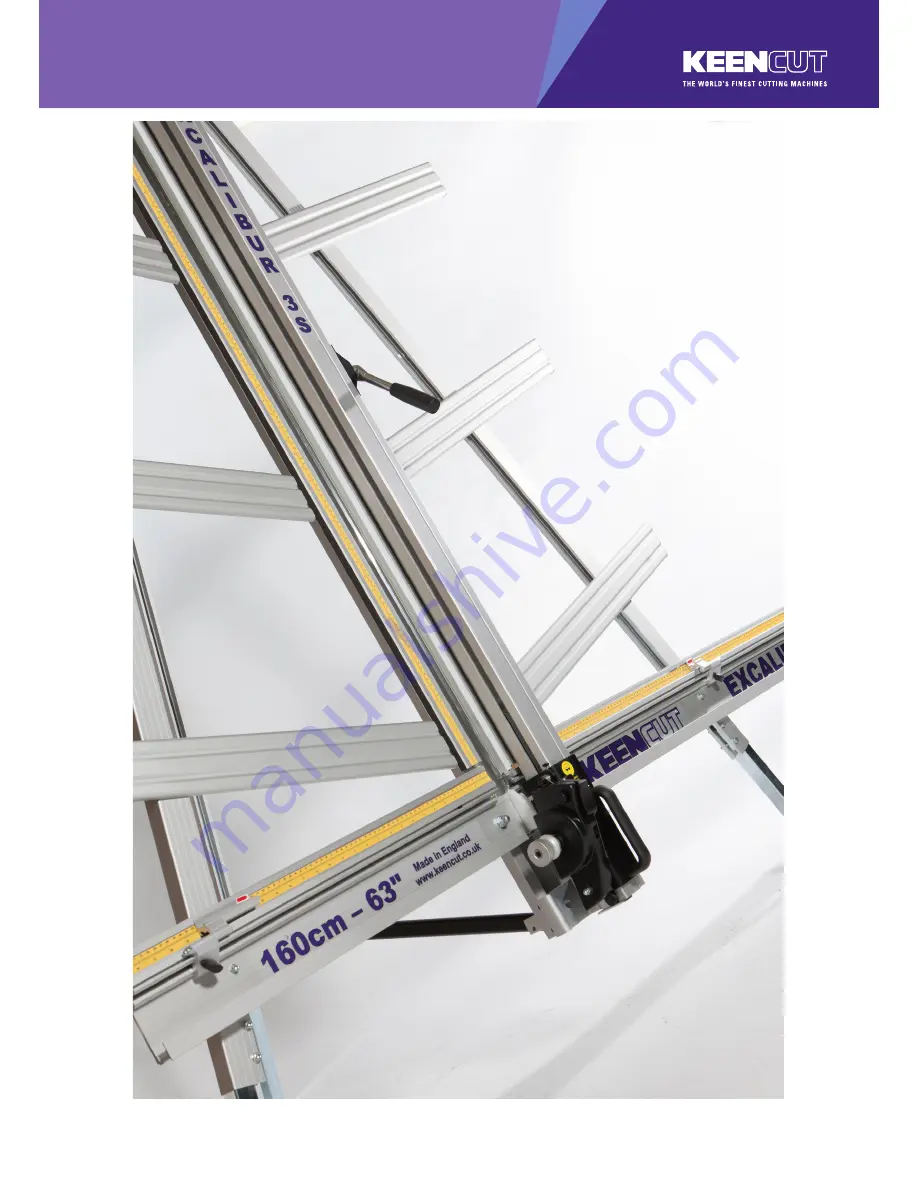
background image

EXCALIBUR 3S


Manual

Single language versions and parts diagrams can be down loaded from www.keencut.co.uk

Thank you for choosing the Keencut Excalibur 3S. Every 

effort has been made to bring you a precision engineered 

product with the promise of many years of valuable         

service. In order to obtain maximum benefit from your          

machine please read these instructions carefully. For advice 

and assistance or replacement parts please contact your 

distributor or Keencut. 

PLEASE NOTE THIS IS A TEMPORARY MANUAL

Summary of Contents for EXCALIBUR 3S

Page 1: ...ur 3S Every effort has been made to bring you a precision engineered product with the promise of many years of valuable service In order to obtain maximum benefit from your machine please read these instructions carefully For advice and assistance or replacement parts please contact your distributor or Keencut PLEASE NOTE THIS IS A TEMPORARY MANUAL ...

Page 2: ...g kit 4 Squaring 4 1 Checking the machine for squareness 4 2 Adjusting the squareness 5 Calibration 5 1 Calibrating the vertical scale 5 2 Calibrating the squaring arm scales 5 3 Fitting the sightline strip 6 Operation 6 1 Using the clamp 6 2 The multi tool cutter and the counterbalance 6 3 Using changing the cutting blade 6 4 Cutting thick material using the ratchet latch 6 5 Using and changing t...

Page 3: ...ring arm 3 Left right hand support arms 4 Vertical scale spare sightline strip 5 Wall mounting bracket 6 Hexagon wrenches 2 0 3 0 5 0 6 0 mm 7 Short support arm screws 8 Long support arm fixing screws 9 Leg fixing screws washers 10 Left hand production stop 11 Right hand production stop 12 Squaring adjuster block fixing screw 13 Spare blades ...

Page 4: ...rd at this stage Remove the main body from the box and lay it on the floor remove the packaging from the bottom end 1 Slacken the bottom two screws on each leg using the 5mm hexagon wrench and extend the telescopic parts to the desired length These can be re adjusted later before fixing the machine to the wall Tighten screws firmly to clamp in position 2 Swing both legs outwards as far as they wil...

Page 5: ... main body 2 Remove the following A One screw from each leg using 5mm hexagon wrench B Two sets of hexagon headed bolts washers and nuts from the main body using 17mm spanners C Remove small screw and two washers from the back of the squaring arm using 3mm hexagon wrench Right hand side ONLY Ⓐ Ⓑ Ⓒ ...

Page 6: ... squaring adjuster block by firstly sliding the steel bar into the opening in the squaring arm then align the heads of the two screws in the leg to fit the top and bottom holes in the adjuster block The screws fixing the squaring arm to the machine should still be loose and allow it some movement to help alignment Insert and tighten the screw in the middle hole 5 Tighten the two hexagon bolts and ...

Page 7: ...ws 4 Fit the support arms NOTE The screws fit into special grooves in the underside of the supports The grooves have teeth on their sides to match the teeth of the screw thread the screw can be fitted in the groove anywhere along its length but be careful to make sure the screw is kept perpendicular to the Support and not screwed in out of line Use one of the long screws in each of the holes along...

Page 8: ...e machine vertical and turn around so the machine is now facing away from the wall 2 The wall mounting bracket should lay flush against the wall Mark the position of the wall fixings with a short pencil 3 Move the machine away and remove the wall mounting bracket 4 Attach the bracket to the wall in the marked position with appropriate fixings then reposition and fasten the machine to the bracket P...

Page 9: ...ded for the following stages 2 Get help to stand the machine up and hold it while the free standing leg is fixed to the bracket using the 6mm hexagon wrench 3 Swing down the stay and attach the fixing block to the back of the main body tighten all three screw on the stay using 5mm 6mm hexagon wrenches 4 Extend the telescopic leg so the machine stands evenly NOTE The free standing kit is an optiona...

Page 10: ...lade on the lower cutting head see section 6 Cut into the top board to produce a cut approximately 3cm 1 long Disengage the cutter using the cutter release lever Lower the cutter and make a similiar cut at the bottom of the board Unclamp and turn the board around like the page in a book and place it back in the machine so the same edge is still on the squaring arm but do not clamp it Align and eng...

Page 11: ...d in the cut on the bottom edge of the board Press down on the board to make sure it is in good contact with the squaring arm 4 Turn the squaring adjustment knob 4 on the right hand leg in the direction described next dependent upon the position of the top two cuts If the second cut is to the right of the first cut turn the adjustment screw clockwise when viewed from underneath If the second cut i...

Page 12: ...o with scissors 2 Remove the paper backing tape and carefully place the rule adjacent to its groove in the main body and with the zero end resting inside the material channel of the squaring arm When aligned stick the rule in its groove 3 Again trim the rule at the bottom end as shown ...

Page 13: ... in the back of the squaring arm if adjustment is necessary 1 Slide the production stop onto the outside edge of the squaring arm as shown 2 Clamp a piece of card in the machine and move the production stop to it 3 Cut the card and measure adjust the sliding scale so that the production stop indicates the measured size 4 Repeat the process for the other side of the machine ...

Page 14: ... paper and starting at the bottom press the strip firmly in the channel provided working upwards and cut off at a convenient height Leave a gap of 18cm 7 and then fit the remainder of the strip 2 Place a piece of firm board up to 6mm 1 4 thick on the machine to bridge the gap running down the back of the main body this needs to be the full height of the clamp 3 Place a piece of card or foam board ...

Page 15: ...ONS Soft materials such as Foamcore boards lightweight card etc Use light to medium pressure The underside of the clamp grips an area nearly 4cm 11 2 wide with a non marking sponge rubber and reasonable force can be applied If in doubt clamp a sample first with the good surface facing outwards Harder materials such as PVC foam board MDF or composite boards such as Dibond Use medium to heavy pressu...

Page 16: ...ent cutter pull the turret handle out to the left about 6mm 1 4 and rotate in either direction the turret will click into the correct position for the cutter indicated Please note that there are three positions on the turret but only two positions are used on this version of the Excalibur 2 The indicator label seen in the cutter guard window shows which cutter is active 3 The counterbalance can be...

Page 17: ...ad locking knob 3 Turn the turret turn until blade is pointing towards you and unlock the blade clamping screw The support plates can be adjusted by sliding the black pin in the slot Move the plates to suit the material For cutting most materials the support plates can be set about 12mm 1 2 from the blade tip Changing the cutting blade 4 Unlock and swing down the cutter guard rotate the turret so ...

Page 18: ...ting PVC foam boards THICKNESS TAKE 3MM 1 8 Initial surface cut 1 additional cut 5MM 1 4 Initial surface cut 1 or 2 additional cuts 10MM 3 8 Initial surface cut 3 or 4 additional cuts 3 Should you engage the cutter by mistake or for any reason want to disengage the cutter without moving it to the bottom of the machine pull down the cutter release lever 4 For some operations such as scoring acrylic...

Page 19: ...pply thumb pressure to the cutter and draw the blade down the material in one continuous motion 4 Remove the plastic from the machine and snap it by hand CAUTION ALWAYS USE HAND AND EYE PROTECTION WHEN SNAPPING PLASTIC Changing the scoring blade Unlock and swing down the cutter guard rotate the turret so the scoring blade is facing outwards 4 Release the blade clamping screw 5 Eject the medium dut...

Page 20: ...m grip and then push the cutter down through the material without stopping The cutting wheels generally last more than a year with average use but this is dependant upon daily use and the material being cut The signs the wheels are wearing out are A rough finish predominantly on the right hand side of the cut with flaking on material such as MDF The bottom of the cut bursting out rather than being...

Page 21: ...cutter at waist height and place a 2mm hexagon wrench on the top adjustment screw Move the cutting head up and down and tighten the scew very gradually until the cutting head dows not fall under its own weight Loosen the screw by the smallest amount you can until it does fall under its own weight Repeat the process with the other three adjustment screws A Adjusting the clamp pressure 2 The pressur...

Reviews: