background image

Q.5.62  February 2021

therm

solutions

KE2 Edge Manager 

(KE2-EM35)

Overview, Installation, and Setup Instructions V1.1 PN 21634

© Copyright 2021 KE2 Therm Solutions, Inc., Washington, Missouri 63090
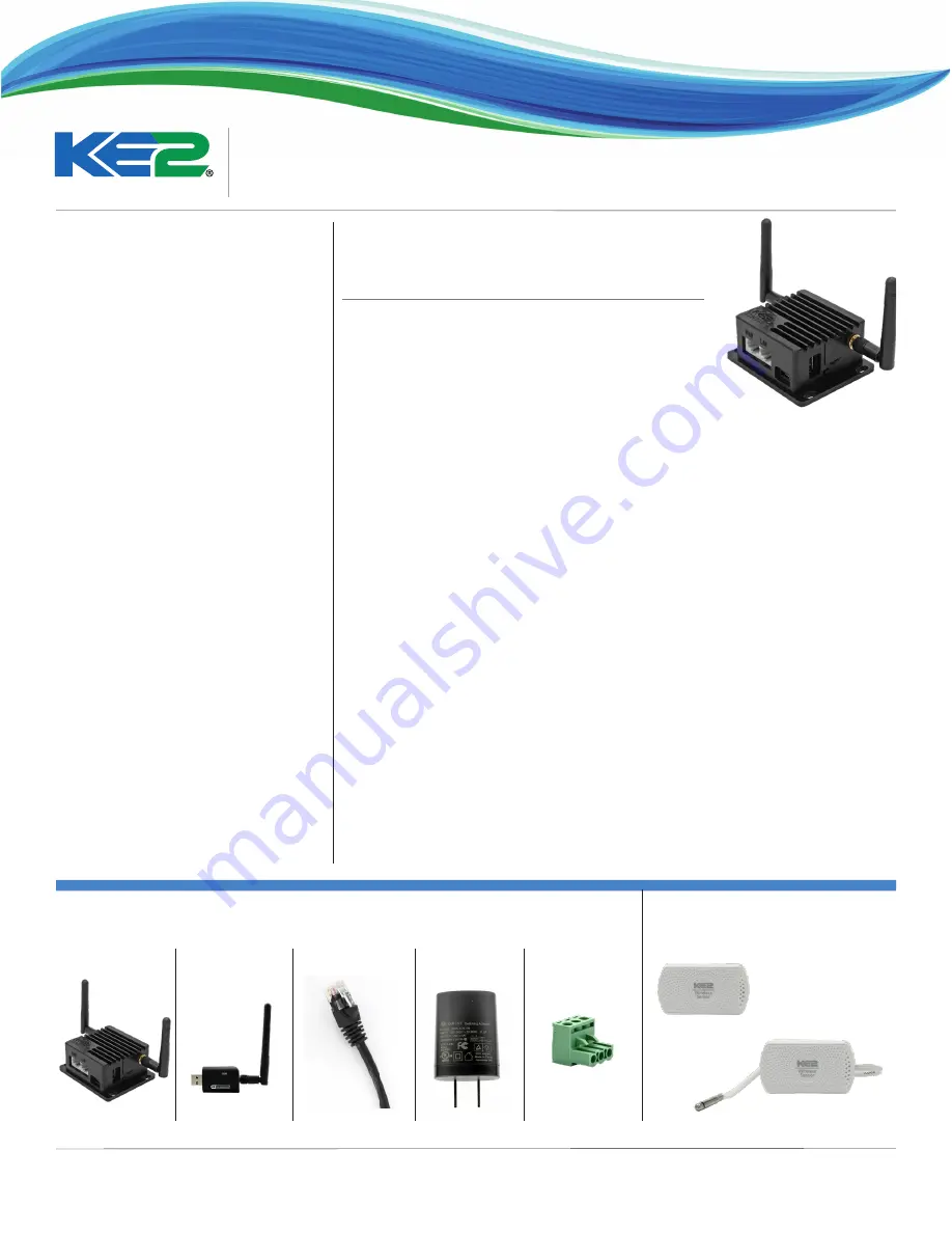
KE2-EM35

KE2 Therm’s Edge Manager - 35 is the perfect 

addition to your Refrigeration Network. 

When the KE2-EM35 is connected to the same network as KE2 

Therm devices, it immediately and automatically scans and 

finds all KE2 Therm controllers – Ethernet and Serial (Modbus)*, 

or KE2 Wireless Sensors.


½

Display a Local Area Dashboard showing controllers 

connected to the customer’s network


½

Connect controllers to KE2 SmartAccess customer portal 

without requiring controller upgrades


½

Send e-mail Alarms to multiple e-mail recipients


½

View Serial (Modbus) devices in a webpage, make changes to 

setpoints and receive alerts via e-mail or text message


½

Local data logging with an option for Advanced data logging 

to MQTT server, SQL server, or Amazon services


½

Wirelessly tether to the local network (Wirelessly connect a controller to existing Wi-Fi)


½

BACnet Integration (currently for KE2-Evap Efficiency & sensors only)


½

Statically assign IP addresses to both WAN and LAN ports

The KE2-EM35 allows customers to locally view all of their controllers/sensors in a single 

view, without a recurring fee.  Additionally, KE2-EM35 enables customers to access their 

controllers over the internet, by functioning as a conduit to KE2 SmartAccess (available for 

a nominal monthly charge.)

* Serial (Modbus) devices must be enabled, see Page 8.

Contents:


½

Introduction, Features & Benefits 

 - Page 1


½

KE2-EM35 Kit Contents 

 - Page 1


½

Options for Connecting to the KE2-EM35

 - Page 2 to 6


¨

Option 1 

-  Connecting Only Serial (Modbus) Controllers - NO 

Internet


¨

Option 2 

-  Connecting Only Serial  (Modbus) Controllers - 

WITH Internet


¨

Option 3 

- Factory Assigned 10.10.x.x on LAN - NO Internet


¨

Option 4 

- Factory Assigned 10.10.x.x on LAN - WITH Internet


¨

Option 5 

-  Controllers Connected & Addressed on Customer 

Network


¨

Option 1 &  3 Combined 

- Connecting Serial (Modbus) & 

Factory 10.10.x.x Controllers - NO Internet


¨

Option 2 &  4 & 5 Combined 

- Connecting Serial (Modbus) & 

Customer Connected Controllers 


¨

Example o f Connecting KE2 Wireless Sensors 

- Available 

will all Options


½

Back Label Information  - Page 7


½

Access the Local Dashboard - Page 7


½

Serial (Modbus) Access - Page 8-9


½

Remote Access Setup - Page 10-13


½

Manage E-mail Alerts - Page 14-16


½

Data Logging  - Page 16


½

Advanced Logging  - Page 17


¨

Option A - MQTT Settings


¨

Option B - MSSQL


¨

Option C - Push Settings


½

BACnet 

- Page 18


½

System

 - Page 18-19


¨

Wireless Tethering


Option 1 - Tethering to Available SSID


Option 2 - TetAp Mode


Option 3 - Tethering to Hidden SSID


Tethering with 802.1x Authentication


¨

Static IP Addressing WAN Port


½

Credentials: Changing User Name & Password - Page 20


½

Field Update Process - Page 21 


½

Allowing Vendor Assist - Page 22 


½

Appendix A Serial (Modbus) Configuration - Page 23


½

Appendix B Serial (Modbus) Wiring - Page 24

Connecting up to 35 KE2 Therm controllers and 

sensors in one view, and letting you access and 

control each individual device.

Power Plug

5ft. Ethernet Cable

KE2-EM35  

Kit pn 21634

 - includes the KE2-EM35 & Accessories shown below 

Kit pn 21660

 -  includes the KE2-EM35 & Accessories shown below, plus (3) KE2 Wireless Sensors pn 21632, 

& (2) KE2 Wireless Sensors with Remote Probe shown at right

pn 21632 - Individual Sensor 

pn 21687 - 10-pack of Sensors

pn 21633 - Individual Sensor

pn 21688  - 10-Pack of Sensors 

KE2 Wireless Sensor w. 

Remote Probe

Wireless Sensors 

(Sold separately, in 10-packs or included 

in KE2-EM35 Kit pn 21660)  

KE2 Wireless Sensor

Blue Tooth Adapter

RS45 Connector

Summary of Contents for KE2-EM35

Page 1: ...ial Modbus Controllers NO Internet Option 2 Connecting Only Serial Modbus Controllers WITH Internet Option 3 Factory Assigned 10 10 x x on LAN NO Internet Option 4 Factory Assigned 10 10 x x on LAN WITH Internet Option 5 Controllers Connected Addressed on Customer Network Option 1 3 Combined Connecting Serial Modbus Factory 10 10 x x Controllers NO Internet Option 2 4 5 Combined Connecting Serial ...

Page 2: ...o a switch then con nected to LAN port Internet provided by connecting WAN port to customer network or tethering to existing in house Wi Fi Features Access Access to controllers locally from the KE2 EM35 Connect via wireless or LAN port to see Dashboard of con nected controllers Enable WAN access to navigate to the KE2 EM from local network Alerting and publish to KE2 SmartAccess Using the EM35 IP...

Page 3: ... B Setup Manage EM Installing the KE2 EM35 Option 2 Connecting Only Serial Modbus Devices WITH Internet WAN LAN A B Sh LAN All Clear Evaporator Fan Off ABC Contracting 888 555 3358 System Mode Cool Superheat 0 0 F Suct Pressure 96 2 F Suct Temp 87 7 F PC Laptop Power Plug For proper daisy chain technique see Page 24 Serial ModBus Controllers KE2Temp Air Defrost KE2Temp Valve Control KE2 LowTemp KE...

Page 4: ...ACK TM thermsolutions Evaporator Efficiency Press and hold for manual defrost Installing the KE2 EM35 Option 3 Read Factory Assigned 10 10 x x DHCP on LAN NO Internet Installing the KE2 EM35 Option 4 Read Factory Assigned 10 10 x x DHCP on LAN WITH Internet WAN LAN KE2 Switch to LAN LAN Power Plug Connect wirelessly to the EM Network ABC Contracting 888 555 3358 System Mode Cool Superheat 0 0 F Su...

Page 5: ...tablet when wirelessly connected to the KE2 EM35 ENTER BACK TM thermsolutions Evaporator Efficiency Press and hold for manual defrost ENTER BACK TM thermsolutions Evaporator Efficiency Press and hold for manual defrost Installing the KE2 EM35 Option 1 3 Combined Connecting Serial Modbus Read Factory Assigned 10 10 x x DHCP Controllers NO Internet EACH DEVICE MUST HAVE A SEPARATE UNIQUE Serial Modb...

Page 6: ...up A Setup Manage EM ENTER BACK TM thermsolutions Evaporator Efficiency Press and hold for manual defrost ENTER BACK TM thermsolutions Evaporator Efficiency Press and hold for manual defrost Installing the KE2 EM35 Option 2 4 5 Combined Connecting Serial Modbus Customer Connected Controllers EACH DEVICE MUST HAVE A SEPARATE UNIQUE Serial Modbus ADDRESS See Appendix B for instructions WAN LAN A B S...

Page 7: ...y connect to that control ler s Home Page The user s web browser will launch a new tab and open the controllers MasterView giving immediate access to view the controller as well as make changes Toreturntothedashboard eitherclickon theDashboardtab orclosethecurrenttab Similartothecontrollersthemselves the KE2 EM35 can also be viewed online us ing either port forwarding or through a Virtual Private ...

Page 8: ...s you can access the web page for the con troller by clicking on COM1 x from either the Management Console or the Dashboard for published devices When you open the COM1 x you will see the web page in either Simple or Advanced View In Simple View you will see the System State as individual icons This is the current state of the device To access Advanced View click on the Show Advanced View TClick o...

Page 9: ...e_namechangesyouwill be prompted for the Modbus Device Login Defaults are ke2admin ke2admin unless they were changed on the au thentication screen NOTE This is a one time login for your active session The first setpoint that s changed prompts you for the pass word Additional setpoint changes on that controller or other Serial Modbus controller s will not prompt for the password For security purpos...

Page 10: ...mart Access automatically connects to your personal web portal providing a dashboard of the controllers you publish with the KE2 EM35 For questions pertaining to the Access feature click on the near the top right on the screen A description of the Access page fea tures is displayed Portal The portal is the internet address used to access the controllers remotely This should NEVER be changed withou...

Page 11: ...reenshot when accessing via cell phone 6 5 6 To publish controllers to KE2 Smart Access click the cloud to the left of the controller you want to publish Clicking on the arrow next to your portal name or entering smartaccess ke2th erm net in your web browser will take you to the site Use the site name and credentials you setup Steps 3 and 4 on page 10 to access your site 7 ...

Page 12: ...s 8 Select the Fields drop down to custom ize the dashboard Show only the fields that are important to you by clicking on the field name and checking or un checking the boxes Get alerts when your controller no lon ger checks in with KE2 SmartAccess server By checking the Disconnected box under State an e mail will be sent if the controller does not check in with our server for a matter of 10 minut...

Page 13: ...arms drop down and enter the e mail addresses When a controller sensor goes into alarm an e mail notification is sent to everyone on the list NOTE This is not required if Alarm no tifications were already setup on the KE2 EM35 Click the Licenses drop down to easily purchase KE2 Smart Access For additional information on KE2 Smart Access see bulletin Q 1 34 KE2 Smart Access Customizing and Setup 12...

Page 14: ...ingle point to enter e mail infor mation up to 35 controllers wire less sensors Manage the e mail addresses re ceiving alerts Set who the e mail is from Elect to either use KE2 Therm s e mail server or a customer provid ed server Navigate to the Manage screen To enable alerting click the box next to Alerts For questions pertaining to the Alerts click on the near the top right on the screen 2a 2 1 ...

Page 15: ...desired To The e mail addresses receiving the e mail alerts should be entered into this field Multiple addresses should be separated with a comma as shown From If the default sender creates confu sion for the party parties receiving the e mails it can be changed to re flect the desired information Please note Only selected control lers will send alerts Click the bell to the left of the device you ...

Page 16: ...sername Enter the username for the account being used for authen tication to the e mail server Password The credentials for the Username being used for authentication TLS This option is selected when using secure e mail STARTTLS This option will upgrade insecure connec tions to SSL TLS When the proper information has been entered the e mail service can be tested using the Test button Clears alarms...

Page 17: ...63090 KE2 EdgeManager KE2 EM35 Overview Installation and Setup Instructions Advanced Logging Logging to local servers or Amazon online account Option A MQTT Settings Option B MSSQL Option C Push Settings A B C Record all available fields for controllers sensors to Advanced Logging Servers ...

Page 18: ... Mode System Wi Fi ON OFF switch The KE2 EM35 doesn t have an external switch like the KE2 LDA Turn Wi Fi ON OFF Tether AP and Tether options Process to Tether Tether AP or Tether What s the difference Tether AP Recommended to wire to LAN but it can be done wirelessly Will complete the tether to Wi Fi and present the EM s SSID to connect to in the future Tether Only Must be wired to the LAN to com...

Page 19: ...ridging to 802 1x Authentication Click in the Wi Fi section and select the SSID that uses 802 1x Authentication Enter Identity and Password Check the Tether AP or the Tether box to complete the connection If using Tether only please wire into LAN A B C A B B C Static LAN Assign a static IP Address to the LAN Port Similar to Static WAN All fields must be keyed in if not designated as optional anyth...

Page 20: ...up Restore Devices Control Devices and Coordinate Devices All which will be described below Backup Restore Devices Used for updating process Backs up the Settings and Setpoints pages for re store after updating controller to lat est firmware Control Devices Gives the ability to make mass changes across multiple controllers Example On the red but ton select a setpoint In this example I chose Room t...

Page 21: ...rected to the Login page NOTE If login credentials are misplaced the only option is to hold the reset button and reset the KE2 EM35 to factory settings i e ke2admin for all User and Passwords This will also reset the wireless creden tials to those listed on the back label of the KE2 EM35 1 3 2 Credentials for Manage Sensors Serial Modbus In the Credentials section for user security purposes the Ma...

Page 22: ...ng and hold ing the reset button on the side of the device Factory Reset By right clicking this but ton and following the prompts will re boot the device Update Firmware EM35 must have an internet connection By clicking this but ton and following the prompts will use the internet connection to download and update the device Upload Firmware For EM35 with no internet connection Update file can be se...

Page 23: ...tup Instructions From the dashboard click Go to Management Console Use current login credentials ThisbringsyoutotheManagement Console Click Update Firmware button Click Start 4 5 Click Reboot During the update and reboot process the LEDs will blink in sequence IMPORTANT Do not power cycle the KE2 EM35 during this process 1 2 3 Field Update Process ...

Page 24: ... the Clear button will clear all unpublished devices and force a re scan This will refresh the list to show any newly connected or disconnected devices This will give you an up to date view of connected devices without disrupting the published devices 2 Stop Clicking the Stop button will clear all devices and force a re scan You will need to republish your devices after clicking the Stop button Th...

Page 25: ...ue Use the button to move to the next digit Again change the value using the or arrow Avail able addresses are 2 to 247 When address is set to the preferred value Ex 24 press and hold for 3 seconds to save the address 4 2 Example The controller will return to the Adr screen when the setting is saved r d A The setting change can be verified by pressing the button To exit press the button several ti...

Page 26: ... USB adapter into the KE2 EM35 STEP 6 Power the KE2 EM35 Appendix B Serial Modbus Wiring When connecting Serial Modbus devices wire the devices using the daisy chain method WAN LAN USB BlueTooth Adapter WAN LAN Power Plug USB BlueTooth Adapter WAN LAN A B Sh Do not connect the shield wire to any of the controllers Shield to shield using a wire nut A B Sh Sh A B Sh A B Sh A B Sh A B Sh A B Sh A B S...

Reviews: