KANSAI SPECIAL BLX2202, Instruction
The Kansai Special BLX2202 Instruction Manual is available for free download on our website. This comprehensive manual provides detailed guidelines on operating and maintaining the BLX2202 sewing machine. Get the most out of your Kansai Special product by downloading the manual from manualshive.com, your go-to source for user manuals.
Share
Download


Reviews:
No comments
Related manuals for BLX2202

S750
Brand: Janome Pages: 41

3704-2/02
Brand: Pfaff Pages: 122

Rotary 1202
Brand: White Pages: 44

i-Qon
Brand: Ash Pages: 30

BOX MONETIERA
Brand: Saeco Pages: 32

Ninja warrior 1200PSI NWCU1312N
Brand: Prochem Pages: 44

2D-HD
Brand: Edco Pages: 12

SPEED SCRUB
Brand: Nobles Pages: 69

PUNCH-BIND
Brand: JBI Pages: 36

Snack Safety Point SVE SSP
Brand: SandenVendo Pages: 44

LK-1941
Brand: JUKI Pages: 126

DU-1481 Series
Brand: JUKI Pages: 34

FO-150
Brand: Sharp Pages: 44

FO-1530
Brand: Sharp Pages: 105

Sanfax 200
Brand: Sanyo Pages: 44

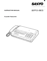
SFX-33
Brand: Sanyo Pages: 63
SFX-30
Brand: Sanyo Pages: 74

SFX-30
Brand: Sanyo Pages: 77


