JUKI DU-1481 Series, Instruction Manual
The JUKI DU-1481 Series Instruction Manual is a valuable resource for owners of this versatile sewing machine. This comprehensive manual provides detailed step-by-step instructions and troubleshooting tips. Download it for free from manualshive.com to conveniently access all the necessary information needed to unlock the full potential of your JUKI DU-1481 Series.
Share
Download


Reviews:
No comments
Related manuals for DU-1481 Series

F100
Brand: UNITED Pages: 15

Panafax UF-8000
Brand: Panasonic Pages: 187
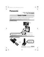
KX-TCD820FX
Brand: Panasonic Pages: 6
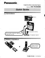
KX-TCD820E
Brand: Panasonic Pages: 6

DP-180
Brand: Panasonic Pages: 65

EXPRESSCARD 1000
Brand: Magtek Pages: 37

CHARGER 2022 ABLT
Brand: NSS Pages: 16

RHINO RD 160
Brand: ROOTS Pages: 164
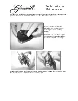
Bobbin Winder
Brand: Gammill Pages: 3

HZL-T100
Brand: JUKI Pages: 28

Advance BU800
Brand: Nilfisk-Advance Pages: 2

147-29
Brand: Singer Pages: 53

DES-WA50
Brand: NaOClean Pages: 20

DYNAMO
Brand: Pacific Steamex Pages: 12

P5721
Brand: Messina Pages: 47

LS-5500HR
Brand: Life Fitness Pages: 3

FAST 01 NEW
Brand: UR FOG Pages: 21

Visys 25205RE1
Brand: RCA Pages: 2


