background image


Contents 


New Energy Requirement 
SUPER DC INVERTER SERIES 

Service Manual 2012 
LFIS-B-1211 


Summary of Contents for SUPER DC INVERTER SERIES

Page 1: ...Contents i New Energy Requirement SUPER DC INVERTER SERIES Service Manual 2012 LFIS B 1211 ...

Page 2: ...ii General Information ...

Page 3: ...eneral Information 1 Part 2 Indoor Units 6 Part 3 Outdoor Units 41 Part 4 Installation 50 Part 5 Electrical Control System 78 The specifications designs and information in this book are subject to change without notice for product improvement ...

Page 4: ......

Page 5: ...LFIS B 1211 General Information General Information 1 Part 1 General Information 1 Model Lists 2 2 External Appearance 3 2 1 Indoor Units 3 2 2 Outdoor Units 3 3 Nomenclature 4 4 Features 5 ...

Page 6: ...l Outdoor unit Model Compressor type Compressor Brand Matched indoor units KOU 18HFN1 QRC4 Rotary GMCC KCD 18HRFN1 QRC4 KTB 18HWFN1 QRC4 KUE 18HRDN1 QRC4 KOU 24HFN1 QRC4 Rotary GMCC KCD 24HRFN1 QRC4 KTB 24HWDN1 QRC4 KUE 24HRDN1 QRC4 MOU 24HFN1 QRC8 Rotary GMCC KCD 24HRFN1 QRC8 KUE 24HRFN1 QRC8 MOU 36HFN1 QRC4 Scroll Mitsubishi KCD 36HRFN1 QRC4 KTB 36HWFN1 QRC4 KUE 36HRFN1 QRC4 MOU 36HFN1 RRC4 Scro...

Page 7: ...LFIS B 1211 External Appearance General Information 3 External Appearance 1 2 Indoor Units Super slim cassette Duct Ceiling Floor 2 2 Outdoor Units Single fan outdoor unit ...

Page 8: ... Condition Designed Time A Time A Designed B Time B Designed C Time C Designed D Time D Designed Product Category C Cassette Type V AHU Type T Duct Type F Console Type U Ceiling Floor Type H High Static Pressure Duct Type Midea 3 2 Outdoor Unit M O U T 36 H D N1 R Power Supply Q 220 240V 1N 50HZ R 380 420V 3N 50Hz N 220 230V 1N 60Hz D 220V 3N 60Hz C 380 420v 3N 60HZ Refrigerant N1 R410A R22 D DC I...

Page 9: ...nction is standard for the indoor units 4 4 Standard auto restart function and follow me function 4 5 Slim cassette with standard remote controller wire controller and CCM for optional Med Duct and HESP duct with standard wired controller remote controller and CCM for optional 4 6 Standard anti cold air function 4 7 Standard auto defrosting function 4 8 Standard self diagnose function 4 9 Standard...

Page 10: ...Indoor Units LFIS B 1211 6 Indoor Units Part 2 Indoor Units Super Slim Cassette Type 7 Duct Type 20 Ceiling Floor Type 33 ...

Page 11: ...te Type Indoor Units 7 Super Slim Cassette Type 1 Features 8 2 Dimensions 12 3 Service Space 13 4 Wiring Diagrams 14 5 Electric Characteristics 15 6 Sound Levels 16 7 Accessories 17 8 The Specification of Power 18 9 Field Wiring 19 ...

Page 12: ... lifting panel design more convenient to clean and maintain the filter optional Old Cassette New slim cassette Volume change Dimension 18K 24K 840 230 840 18K 24K 840 203 840 13 3 30K 840 300 840 30K 840 203 840 47 7 36K 48K 840 300 840 36K 48K 840 245 840 22 4 1 2 Fresh air intake function Fresh air fulfills air quality more healthy and comfortable Ventilation motor is optional to increase the ef...

Page 13: ... be switched on or off by remote controller When pressing the Clean Air button on the remote controller Ionizer will work and the indicator light on display board will shine New air intake I Io on ni iz ze er r g ge en ne er ra at to or r c co on nn ne ec ct to or r V Ve en nt ti il la at ti io on n m mo ot to or r c co on nn ne ec ct to or r ...

Page 14: ...gn Reserve external air duct more flexible for the air supply 1 5 Built in draining pump Due to the improvement of structure more convenient to repair or replace the draining pump Built in draining pump to make sure condensed water drain out reliably Draining Pump ...

Page 15: ...rd with error code indication function Better man machine conversation interface Undated structure design 4 way wire layout design no raised part at backside more convenient to place the wires and install the device Remote controller is optional without auto lifting panel function 1 8 Twins Combination The units can be installed as Twin systems one outdoor unit can connect with two indoor units Th...

Page 16: ...Dimensions LFIS B 1211 12 Indoor Units 2 Dimensions Model A H 18 205 235 24 205 235 36 245 275 ...

Page 17: ...LFIS B 1211 Service Space Indoor Units 13 3 Service Space 1000mm 1000mm 1000mm 1000m m ...

Page 18: ...Wiring Diagrams LFIS B 1211 14 Indoor Units 4 Wiring Diagrams KCD 18HRFN1 QRC4 KCD 24HRFN1 QRC4 KCD 24HRFN1 QRC8 KCD 36HRFN1 QRC4 ...

Page 19: ...ectric Characteristics Model Indoor Unit Power Supply Hz Voltage Min Max MFA KCD 18HRFN1 QRC4 50 220 240 198 254 15 KCD 24HRFN1 QRC4 50 220 240 198 254 15 KCD 24HRFN1 QRC8 50 220 240 198 254 15 KCD 36HRFN1 QRC4 50 220 240 198 254 15 Notes MFA Max Fuse Amps A ...

Page 20: ...S B 1211 16 Indoor Units 6 Sound Levels 1 0m Microphone Model Noise Power dB A Noise level dB A H M L KCD 18HRFN1 QRC4 58 47 43 36 KCD 24HRFN1 QRC4 59 48 44 40 KCD 24HRFN1 QRC8 64 48 44 40 KCD 36HRFN1 QRC4 65 54 50 48 ...

Page 21: ...Out let pipe sheath 1 Out let pipe clasp 1 Remote controller Its Frame Remote controller Its Frame 1 Remote controller holder 1 Mounting screw ST2 9 10 C H 2 Remote controller manual 1 Alkaline dry batteries AM4 2 Others Owner s manual 1 Installation manual 1 Network wires 1 Installation accessory The product you have might not be provided the following accessories Expansible hook 4 Installation h...

Page 22: ...Hz 220 240V 50Hz 220 240V 50Hz POWER WIRING mm 2 3 1 0 3 1 0 3 1 0 CIRCUIT BREAKER A 15 15 15 OUTDOOR UNIT POWER Phase 1 phase 1 phase 3 phase Frequency and Voltage 220 240V 50Hz 220 240V 50Hz 380 420V 50Hz POWER WIRING mm 2 3 2 5 3 4 0 5 2 5 CIRCUIT BREAKER A 30 40 30 Indoor Outdoor Connecting Wiring Weak Electric Signal mm 2 3 0 5 3 0 5 3 0 5 Indoor Outdoor Connecting Wiring Strong Electric Sign...

Page 23: ...LFIS B 1211 Field Wiring Indoor Units 19 9 Field Wiring ...

Page 24: ...ndoor Units Duct Type 1 Features 21 2 Dimensions 24 3 Service Space 25 4 Wiring Diagrams 26 5 Static Pressure 27 6 Electric Characteristics 28 7 Sound Levels 29 8 Accessories 30 9 The Specification of Power 31 10 Field Wiring 32 ...

Page 25: ...ver from bottom to rear side or from rear to the bottom in order to matching the installation condition 1 3 Fresh air intake function Install one duct from the reserved fresh air intake to outdoor Continually inhale the fresh air to improve the quality of the indoor air fulfills air quality more healthy and comfortable 1 4 Easy maintenance Clean the filter Optional standard product without filter ...

Page 26: ...rved remote on off and central control ports Reserved remote on off ports and central control ports can connect the cable of an on off controller or a central controller to realize remote on off control function or group control function 1 6 Built in drain pump Optional Built in drain pump can lift the water to 750mm upmost It s convenient to install drainage piping under most space condition Moto...

Page 27: ...distance of 10m The unit will realized remoter control The wired controller and the display board can display the error code or production code when the chips detect some failure 1 8 Twins Combination The units can be installed as Twin systems one outdoor unit can connect with two indoor units The indoor units can be combined in any of the different available ratings Display 750mm upmost Wired Con...

Page 28: ...C L M Capacity KBtu Outline dimension mm Air outlet opening size Air return opening size Size of outline dimension mounted plug A B C D E F G H I J K L M 18 24 920 270 635 570 65 713 35 179 815 260 20 960 350 30 36 1140 270 775 710 65 933 35 179 1035 260 20 1180 490 ...

Page 29: ...S B 1211 Duct Type Indoor Units 25 3 Service Space Ensure enough space required for installation and maintenance All the indoor units reserve the hole to joint the fresh air pipe The hole size as following ...

Page 30: ...Duct Type LFIS B 1211 26 Indoor Units 4 Wiring Diagrams KTB 18HWFN1 QRC4 KTB 24HWDN1 QRC4 KTB 36HWFN1 QRC4 ...

Page 31: ...w speed 10 20 30 40 50 60 70 80 90 Pa 800 900 1000 1100 Air volume m h 3 External static pressure Pa High speed Mid speed 1200 1500 700 36 000Btu h 2400 2200 1600 1400 Low speed 10 20 30 40 50 60 70 80 90 1100 Air volume m h 3 External static pressure Pa High speed Mid speed 1200 1800 2000 Super high speed Pa ...

Page 32: ...or Units 6 Electric Characteristics Model Indoor Unit Power Supply Hz Voltage Min Max MFA KTB 18HWFN1 QRC4 50 220 240 198 254 15 KTB 24HWDN1 QRC4 50 220 240 198 254 15 KTB 36HWFN1 QRC4 50 220 240 198 254 15 Note MFA Max Fuse Amps A ...

Page 33: ...door Units 29 7 Sound Levels Suction Discharge Microphone 1 4m Concealed Duct Type Duct Duct Model Sound Power dB A Noise level dB A H M L KTB 18HWFN1 QRC4 59 40 38 36 KTB 24HWDN1 QRC4 58 43 37 34 KTB 36HWFN1 QRC4 64 48 44 40 ...

Page 34: ...f insulation sheath 2 Binding tape 1 Seal sponge 1 Drainpipe Fittings for cooling heating Drain joint 1 Seal ring 1 Wired controller Its Frame Wired controller 1 Others Owner s manual 1 Installation manual 1 EMS It s fitting Magnetic ring twist the electric wires L and N around it to five circles 1 ...

Page 35: ...40V 50Hz 220 240V 50Hz POWER WIRING mm 2 3 1 0 3 1 0 3 1 0 CIRCUIT BREAKER A 15 15 15 OUTDOOR UNIT POWER Phase 1 phase 1 phase 3 phase Frequency and Voltage 220 240V 50Hz 220 240V 50Hz 380 420V 50Hz POWER WIRING mm 2 3 2 5 3 4 0 5 2 5 CIRCUIT BREAKER A 30 40 30 Indoor Outdoor Connecting Wiring Weak Electric Signal mm 2 3 0 5 3 0 5 3 0 5 Indoor Outdoor Connecting Wiring Strong Electric Signal mm 2 ...

Page 36: ...Duct Type LFIS B 1211 32 Indoor Units 10 Field Wiring ...

Page 37: ...e Indoor Units 33 Ceiling Floor Type 1 Features 34 2 Dimensions 35 3 Service Space 36 4 Wiring Diagrams 37 5 Electric Characteristics 38 6 Sound Levels 38 7 Accessories 39 8 The Specification of Power 39 9 Field Wiring 40 ...

Page 38: ...ighting 1 3 Two direction auto swing vertical horizontal and wide angle air flow Air flow directional control minimizes the air resistance and produces wilder air flow to vertical direction The range of horizontal air discharge is widened which secures wider air flow distribution to provide more comfortable air circulation no matter where the unit is set up 1 4 Three level fan speed more humanism ...

Page 39: ...LFIS B 1211 Duct Type Indoor Units 35 2 Dimensions Capacity Btu h A B C D E 18K 24K 1068 675 235 983 220 36K 1285 675 235 1200 220 ...

Page 40: ...Duct Type LFIS B 1211 36 Indoor Units 3 Service Space ...

Page 41: ...LFIS B 1211 Duct Type Indoor Units 37 4 Wiring Diagrams KUE 18HRDN1 QRC4 KUE 24HRDN1 QRC4 KUE 24HRFN1 QRC8 KUE 36HRFN1 QRC4 ...

Page 42: ...24HRDN1 QRC4 50 220 240V 197V 254V 1 25 20 KUE 24HRFN1 QRC8 50 220 240V 197V 254V 1 25 20 KUE 36HRFN1 QRC4 50 220 240V 197V 254V 1 25 20 Remark MCA Min Current Amps A MFA Max Fuse Amps A 6 Sound Levels Ceiling Floor Model Sound Power dB A Noise level dB A H M L KUE 18HRDN1 QRC4 56 40 36 33 KUE 24HRDN1 QRC4 62 50 48 43 KUE 24HRFN1 QRC8 63 50 47 43 KUE 36HRFN1 QRC4 63 52 48 38 ...

Page 43: ...24000Btu h 36000 36000 Btu h INDOOR UNIT POWER Phase 1 phase 1 phase 1 phase Frequency and Voltage 220 240V 50Hz 220 240V 50Hz 220 240V 50Hz POWER WIRING mm 2 3 1 0 3 1 0 3 1 0 CIRCUIT BREAKER A 15 15 15 OUTDOOR UNIT POWER Phase 1 phase 1 phase 3 phase Frequency and Voltage 220 240V 50Hz 220 240V 50Hz 380 420V 50Hz POWER WIRING mm 2 3 2 5 3 4 0 5 2 5 CIRCUIT BREAKER A 30 40 30 Indoor Outdoor Conne...

Page 44: ...Field Wiring LFIS B 1211 40 Part 3 9 Field Wiring ...

Page 45: ...LFIS B 1211 Part 3 Part 3 41 Part 3 Outdoor Units 1 Dimensions 42 2 Service Space 43 3 Piping Diagrams 44 4 Wiring Diagrams 45 5 Electric Characteristics 47 6 Operation Limits 48 7 Sound Levels 49 ...

Page 46: ...Model Unit mm A B C D E F H KOU 18HFN1 QRC4 845 560 335 360 313 324 700 KOU 24HFN1 QRC4 895 590 333 355 302 313 862 KOU 24HFN1 QRC8 895 590 333 355 302 313 862 KOU 36HFN1 QRC4 990 624 366 396 340 354 966 KOU 36HFN1 RRC4 990 624 366 396 340 354 966 ...

Page 47: ...LFIS B 1211 Service Space Part 3 43 2 Service Space More than 60cm More than 30cm More than 60cm More than 200cm Air inlet Air inlet More than 30cm Air outlet Wall or obstacle Maintain channel ...

Page 48: ...or T5 Discharge temp sensor T4 Ambient temp sensor INDOOR OUTDOOR Electronic expansion valve CAPILIARY TUBE Accumulator KOU 36HFN1 QRC4 KOU 36HFN1 RRC4 Low pressure switch High pressure switch LIQUID SIDE GAS SIDE HEAT EXCHANGE EVAPORATOR HEAT EXCHANGE CONDENSER Compressor 2 WAY VALVE 3 WAY VALVE 4 WAY VALVE COOLING HEATING T2 Evaporator temp sensor T1 Room temp sensor T3 Condenser temp sensor Acc...

Page 49: ...LFIS B 1211 Wiring Diagrams Part 3 45 4 Wiring Diagrams KOU 18HFN1 QRC4 KOU 24HFN1 QRC4 KOU 24HFN1 QRC4 KOU 36HFN1 QRC4 ...

Page 50: ...Wiring Diagrams LFIS B 1211 46 Part 3 KOU 36HFN1 RRC4 ...

Page 51: ...lectric Characteristics Model Outdoor Unit Hz Voltage Min Max KOU 18HFN1 QRC4 50 220 240V 198V 254V KOU 24HFN1 QRC4 50 220 240V 198V 254V KOU 24HFN1 QRC8 50 220 240V 198V 254V KOU 36HFN1 QRC4 50 220 240V 198V 254V KOU 36HFN1 RRC4 50 380 415V 342V 440V ...

Page 52: ... safety protection features may come into operation and cause the unit to operate abnormally 2 The room relative humidity should be less than 80 If the air conditioner operates beyond this figure the surface of the air conditioner may attract condensation Please set the vertical air flow louver to its maximum angle vertically to the floor and set HIGH fan mode 3 The optimum performance will be ach...

Page 53: ...nd Levels Part 3 49 7 Sound Levels H 1 0m Outdoor Unit Microphone Note H 0 5 height of outdoor unit Model Sound Power dB A KOU 18HFN1 QRC4 65 KOU 24HFN1 QRC4 69 KOU 24HFN1 QRC8 69 KOU 36HFN1 QRC4 69 KOU 36HFN1 RRC4 70 ...

Page 54: ... 3 Indoor unit installation 53 4 Outdoor unit installation Side Discharge Unit 63 5 Refrigerant pipe installation 65 6 Drainage pipe installation 68 7 Vacuum Drying and Leakage Checking 72 8 Additional refrigerant charge 73 9 Engineering of insulation 74 10 Engineering of electrical wiring 76 11 Test operation 77 ...

Page 55: ...t pipe Wiring connection and electric safety checking Test operation Refrigerant pipe installation and insulation Drainage pipe installation and insulation Indoor unit installation location selection Outdoor unit installation location selection Indoor unit installation Outdoor unit installation Refrigerant pipe installation and insulation Drainage pipe installation and insulation ...

Page 56: ...election The place shall easily support the outdoor unit s weight Locate the outdoor unit as close to indoor unit as possible The piping length and height drop can not exceed the allowable value The place where the noise vibration and outlet air do not disturb the neighbors There is enough room for installation and maintenance The air outlet and the air inlet are not impeded and not face the stron...

Page 57: ...nstallation 3 1 1 Service space for indoor unit Model A H Remark 24 30 205 235 R410A and R22 Cooling Cooling Heating 36 48 245 275 R410A and R22 Cooling Cooling Heating 3 1 2 Bolt pitch 3 1 3 Install the pendant bolt Select the position of installation hooks according to the hook holes positions showed in upper picture ...

Page 58: ...gular nuts on the four installation hooks evenly to ensure the balance of the body Use a leveling instrument to make sure the levelness of the main body is within 1 Adjust the position to ensure the gaps between the body and the four sides of ceiling are even The body s lower part should sink into the ceiling for 10 12 mm In general L is half of the screw length of the installation hook Locate the...

Page 59: ...llation 55 3 1 5 Install the panel Remove the grille Remove the 4 corner covers Hang the panel to the hooks on the mainbody If the panel is with auto lift grille please watch the ropes lifing the grille DO NOT make the ropes enwinded or blocked ...

Page 60: ...ely stick on the ceiling to avoid condensate water Hang the air in grill to the panel then connect the lead terminator of the swing motor and that of the control box with corresponding terminators on the body respectively Install the 4 corner covers back Note The panel shall be installed after the wiring connected ...

Page 61: ...city KBtu Size of outline dimension mounted plug L M 24 960 350 30 36 1180 490 48 60 1240 500 3 2 3 Install the pendant bolt Select the position of installation hooks according to the hook holes positions showed in upper picture Drill four holes of Ø12mm 45 50mm deep at the selected positions on the ceiling Then embed the expansible hooks fittings ...

Page 62: ...st the hexangular nuts on the four installation hooks evenly to ensure the balance of the body Use a leveling instrument to make sure the levelness of the main body is within 1 3 2 5 Install the air filter Insert the air filter through the filter slot and fix it with 2 screws 3 2 6 Install the air duct Please design the air duct as below recommended picture ...

Page 63: ...e attached seal sponge as per the indicating place in the following fig and then change the mounting positions of air return panel and air return flange When install the filter mesh please plug it into flange inclined from air return opening and then push up The installation has finish upon filter mesh which fixing blocks have been insert to the flange positional holes ...

Page 64: ... B 1211 60 Installation 3 3 Ceiling floor indoor unit installation 3 3 1 Service space for indoor unit 3 3 2 Bolt pitch Ceiling installation Capacity Btu h D E 18K 24K 983 220 36K 1200 220 48K 60K 1565 220 Wall mounted installation ...

Page 65: ... of Ø12mm 45 50mm deep at the selected positions on the ceiling Then embed the expansible hooks fittings Wall mounted installation Install the tapping screws onto the wall Refer to picture below 3 3 4 Install the main body Ceiling installation The only installation method for the unit with drain pump Remove the side board and the grille Locate the hanging arm on the hanging screw bolt Prepare the ...

Page 66: ...lation Put the side panels and grilles back Wall mounted installation Hang the indoor unit by insert the tapping screws into the hanging arms on the main unit The bottom of body can touch with floor or suspended but the body must install vertically ...

Page 67: ... outdoor unit 4 2 Bolt pitch Model B C D 18K 560 335 360 24K 590 333 355 36K 624 366 396 4 3 Install the Unit Since the gravity center of the unit is not at its physical center so please be careful when lifting it with a sling Never hold the inlet of the outdoor unit to prevent it from deforming Do not touch the fan with hands or other objects ...

Page 68: ...4 Installation Do not lean it more than 45 and do not lay it sidelong Make concrete foundation according to the specifications of the outdoor units Fasten the feet of this unit with bolts firmly to prevent it from collapsing in case of earthquake or strong wind ...

Page 69: ...e section flat and smooth 9 0 Lean Crude Burr o 5 2 5 Insulate the copper pipe Before test operation the joint parts should not be heat insulated 5 2 6 Flare the pipe Insert a flare nut into the pipe before flaring the pipe According to the following table to flare the pipe Pipe diameter Flare dimension A mm Flare shape Min Max 1 4 6 35 8 3 8 7 R0 4 0 8 A 45 ã 90 4 3 8 9 52 12 0 12 4 1 2 12 7 15 4...

Page 70: ...1 4 6 35 144 176 1420 1720 3 8 9 52 333 407 3270 3990 1 2 12 7 504 616 4950 6030 5 8 15 9 630 770 6180 7540 3 4 19 990 1210 9270 11860 5 3For Units with Twins Function 5 3 1 Length and drop height permitted of the refrigerant piping Note Reduced length of the branching tube is the 0 5m of the equivalent length of the pipe Note All used branch pipe must be produced by Midea otherwise it causes malf...

Page 71: ...stallation 67 5 3 2 Size of joint pipes for indoor unit R410a 5 3 3 Size of joint pipes for outdoor unit R410a 5 3 4 The branching pipe must be installed horizontally error angle of it should not large than 10 Otherwise malfunction will be caused ...

Page 72: ...the water flowrate is decided by the capacity of indoor unit Relationship between water flowrate and capacity of indoor unit Capacity x1000Btu Water flowrate l h 12 2 4 18 4 24 6 30 7 36 8 42 10 48 12 60 14 According to the above table to calculate the total water flowrate for the confluence pipe selection For horizontal drainage pipe The following table is for reference PVC pipe Reference value o...

Page 73: ...Too long distance Gas bag 6 2 5 The horizontal pipe layout should avoid converse flow or bad flow Drainage pipe Water flow Drainage pipe Drainage pipe Drain tee Drain tee Water flow Water flow Water flow Water flow Water flow Water flow Water flow Water flow Drain tee Branch pipe Water flow Water flow Keep a certain degree Branch pipe Gas Gas Main pipe Main pipe The correct installation will not c...

Page 74: ...el switch Refer the following picture for installation reference Flexible pipe 300mm Hanger A A Length of vertical pipe 150mm B Lift height the pump head of water pump Down incline pipe B 6 2 8 Blowhole setting For the concentrated drainage pipe system there should design a blowhole at the highest point of main pipe to ensure the condensate water discharge smoothly The air outlet shall face down t...

Page 75: ... pipe at drainage outlet In light of the length of drainage pipe water shall be discharged about 1 minute delayed 2 3 Stop the operation of air conditioner power off the power supply and put the cover of water test hole back to the original place a After stopped the air conditioner 3 minutes check whether there is anything abnormal If drainage pipes have not been distributed properly over back flo...

Page 76: ...h 755mmHg after 1 5 hours of drying check whether there is leakage source 4 Leakage test After the vacuum degree reaches 755mmHg stop vacuum drying and keep the pressure for 1 hour If the indicator of vacuum gauge does not go up it is qualified If going up it indicates that there is moisture or leak source 7 3 2 Special vacuum drying The special vacuum drying method shall be adopted when 1 Finding...

Page 77: ...ngth of the liquid pipe m Note Refrigerant may only be charged after performed the vacuum drying process Always use gloves and glasses to protect your hands and eyes during the charge work Use electronic scale or fluid infusion apparatus to weight refrigerant to be recharged Be sure to avoid extra refrigerant charged it may cause liquid hammer of the compressor or protections Use supplementing fle...

Page 78: ... above 10mm If in hot or wet environment place the layer of insulation should be thicker accordingly 9 1 4 Installation highlights of insulation construction Gas pipe and liquid pipe shall be insulated separately if the gas pipe and liquid pipe were insulated together it will decrease the performance of air conditioner Liquid pipe Insulation meterial Gas pipe The insulation material at the joint p...

Page 79: ...LFIS B 1211 Engineering of insulation Installation 75 cause leakage to damage the house decoration ...

Page 80: ...All field wiring construction should be finished by qualified electrician Air conditioning equipment should be grounded according to the local electrical regulations Current leakage protection switch should be installed Do not connect the power wire to the terminal of signal wire When power wire is parallel with signal wire put wires to their own wire tube and remain at least 300mm gap According t...

Page 81: ...ndoor units The gas side and liquid side stop values are both opened The air conditioner is pre heated by turning on the power 11 3 Test operation Set the air conditioner under the mode of COOLING by remote controller and check the following points Indoor unit Whether the switch on the remote controller works well Whether the buttons on the remote controller works well Whether the air flow louver ...

Page 82: ...Electrical Control System LFIS B 1211 78 Electrical Control System Part 5 Electrical Control System 1 Electrical Control Function 79 2 Troubleshooting 88 3 Controller 117 ...

Page 83: ...3 Temperature protection of compressor discharge When the compressor discharge temp is getting higher the running frequency will be limited as below rules If 102 T5 115 decrease the frequency to the lower level every 2 minutes till to F1 If T5 115 for 10 seconds the compressor will stop and restart till T5 90 1 2 4 Sensor protection at open circuit and breaking disconnection 1 2 5 Indoor fan delay...

Page 84: ...dium 3 0 Ts 24 1 3 2 Cooling Mode 1 3 2 1 Outdoor PMW open angle control The unit is working in cooling mode with the EXV open 300P for 3 minutes then adjusting PMW open angle according to the temperature of compressor discharge every 2 minutes 1 3 2 2 Outdoor fan running rules T4 A DC_FAN_HI_SPD_ADD B DC_FAN_MID_SPD_ADD C DC_FAN_MIN_SPD_ADD D DC_FAN_SLOW_SPD_ADD E DC_FAN_SSLOW_SPD_ADD 23 22 20 28...

Page 85: ...estart 1 3 3 Heating Mode 1 3 2 1 Outdoor PMW open angle control The unit is working in heating mode with the EXV open 300P for 3 minutes then adjusting PMW open angle according to the temperature of compressor discharge every 2 minutes 1 3 3 2 Outdoor fan running rules T4 E DC_FAN_SSLOW_SPD_ADD D DC_FAN_SLOW_SPD_ADD C DC_FAN_MIN_SPD_ADD B DC_FAN_MID_SPD_ADD A DC_FAN_HI_SPD_ADD 21 19 18 16 15 13 1...

Page 86: ...sts for 40 minutes Defrosting action 4 Way valve Indoor fan Outdoor fan 480P PMV PMV running 6 mins with 300P Compressor 10S 30S TimeA 10S no longer than 10min Condition of ending defrosting If any one of following items is satisfied defrosting will stop and the machine will turn to normal heating mode T3 TempQuitDefrost_ADD The defrosting time achieves 10min For 48K model Condition of defrosting ...

Page 87: ...ons 1 Compressor is off 2 T3 TempEnterDefrost_ADD Time2 Time conditions Meet the following conditions 1 Running in heating mode 2 T4 3 3 Compressor is on 4 T3 TempEnterDefrost_ADD Cleared conditions Meet any one of the following conditions 1 Compressor is off and T3 TempEnterDefrost_ADD 2 last fo r 20 minutes 2 Running in cooling mode 3 Compressor is off for 1 hour Condition of entry defrosting ti...

Page 88: ...de can be chosen with remote controller and the setting temperature can be changed between 17 30 In auto mode the machine will choose cooling heating or fan only mode according to ΔT ΔT T1 Ts ΔT T1 Ts Running mode ΔT 2 Cooling 1 ΔT 2 Fan only ΔT 1 Heating Indoor fan will run at auto fan of the relevant mode The louver operates same as in relevant mode If the machine switches mode between heating a...

Page 89: ...en heating the setting temperature decreases 1 be higher than 17 every one hour 2 hours later the setting temperature stops rising and indoor fan is fixed at low speed Anti cold wind function has the priority 1 3 7 3 Operation time in sleep mode is 7 hours After 7 hours the AC quits this mode but doesn t turns off 1 3 7 4 Timer setting is available 1 3 8 Auto Restart function The indoor unit is eq...

Page 90: ...ee the digital display tube will show 70 If the indoor unit is not connected the digital display tube will show 08 Outdoor ambient temp T4 09 Compressor discharge temp Tp The display value is between 30 120 degree If the temp is lower than 30 degree the digital display tube will show 30 If the temp is higher than 99 degree the digital display tube will show single digit and tens digit For example ...

Page 91: ...igital display tube will show 70 If the capacity demand is 0 the digital display tube will show 0 If the indoor unit is not connected the digital display tube will show 20 Condenser pipe temp of 2 indoor unit 21 Condenser pipe temp of 3 indoor unit 22 1 Indoor unit capacity demand code Actual data HP 10 If capacity demand code is higher than 99 the digital display tube will show single digit and t...

Page 92: ...con explanation on indoor display board A5 Duct OPERATION TIMER DEF FAN ALARM Temporary button Operation lamp Timer indicator Infrared signal receiver Alarm indicator PRE DEF indicator cooling and heating type or fan only indicator cooling only type MANUAL Display digital tube 2 1 3 Display board of Up down 4 way Panel 2 1 4 Display board of Ceiling floor indoor unit ...

Page 93: ...p down panel is not closed X O F2 12 Communication malfunction between master unit and slave unit X X F3 13 Other malfunction of master unit or slave unit X X F4 O on X off flash at 5Hz flash at 0 5Hz 2 3 Outdoor unit malfunction Display Malfunction or Protection E0 Outdoor EEPROM malfunction E2 Indoor outdoor units communication error E3 Communication malfunction between IPM board and outdoor mai...

Page 94: ...or the indoor unit 2 4 1 1 Open or short circuit of temperature sensor Check the connections between temperature sensor and PCB Are the connections good Correct the connections No Yes Yes Replace indoor or outdoor PCB Replace the sensor Check the resistance value of the sensor via Appendix 1 Is it normal No ...

Page 95: ...s Yes No No Check whether the power is on Replace outdoor main board Yes Whether the outdoor unit is power on Check whether the communication wire between the indoor and outdoor unit is connected correctly Yes Connect the wiring well or replace the communication wire No Replace the indoor PCB Trouble is solved check if the errors happen again Yes No Outdoor unit malfunction ...

Page 96: ...t the EEPROM well Replace the indoor PCB Shut off the power supply and turn it on 5 seconds later Is it still displaying the error code 2 4 1 4 Full water malfunction If the water level switch is inserted well No Insert the water level switch well If the water level switch is broken Yes Replace the water level switch If the water pump is normal No Replace the water pump Yes No Yes Check PCB board ...

Page 97: ...mally Replace indoor fan motor Check the wires of fan motor Are all the connections good No Yes No Correct the connections No Yes Replace indoor main PCB Is it still displaying the error code Yes Yes Check the voltage between every port and GND port of fan motor connector does it comply with the table No DC motor voltage input and output control chip is inside the motor DC motor voltage input and ...

Page 98: ...aced Otherwise go to step 2 2 Power on and when the unit is in standby measure the voltage of pin4 5 in feedback signal connector If the value is not 5V change the PCB Otherwise go to step 3 3 Rotate the fan by hand measure the voltage of pin1 5 pin 2 5 and pin 3 5 in feedback signal connector If any voltage is not positive voltage fluctuation the fan motor must have problems and need to be replac...

Page 99: ... B 1211 Troubleshooting Electrical Control System 95 2 4 2 For the super slim cassette with up down panel 2 4 2 1 Communication error between indoor unit and up down panel 2 4 2 2 Up down panel is defective ...

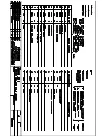
Page 100: ...Troubleshooting LFIS B 1211 96 Electrical Control System 2 4 2 3 Up down panel is not closed ...

Page 101: ...LFIS B 1211 Troubleshooting Electrical Control System 97 2 4 3 For the unit with TWINS function 2 4 3 1 Communication failure between master unit and indoor unit ...

Page 102: ...or the outdoor unit 2 4 4 2 E0 malfunction If the EEPROM chip is welded on PCB replace the PCB directly Otherwise check whether the EEPROM chip plugged in PCB well Yes No Yes Insert the EEPROM well Replace the outdoor main board Outdoor EEPROM malfunction E0 display ...

Page 103: ...e error still displaying after several minutes No Yes Change the outdoor main PCB Power on Is the error extinguished Check all the wirings between indoor and outdoor indoor main PCB and outdoor main PCB following the wiring diagram Are all the wirings connected correctly Is the wiring to the indoor main PCB connected correctly Change the indoor main PCB Yes Change the outdoor main PCB No Is the wi...

Page 104: ...cable earthing Check whether the wire is correct polarity P to P Q to Q E to E No Yes Correct the connection No Check if there s any interference Such as too many lamps power transformers Or the signal wire is too long Yes Remove interference Increase the capacity of anti interference Yes Check whether the signal wire is broken Yes Replace the signal wire Yes Check whether the signal wires insert ...

Page 105: ...M board light Check the signal wire between the IPM module and the main board is it connected good Reconnect and retry Is error still display Replace IPM board and then check whether the system can run normally Replace the electric control box No No No No Yes Trouble is solved No Yes Replace outdoor main board and then check whether the system can run normally No Yes Yes E3 display ...

Page 106: ... whether the resistance of condenser temp sensorT3 is wrong refer to the Appendix 1 Yes Connect the wiring well Yes Judge 2 Outdoor ambient temp sensor T4 is malfunction No Replace outdoor ambient temperature sensor T4 Check whether the wiring of the outdoor ambient temperature sensor T4 is broken off Check whether the resistance of outdoor ambient temperature sensor T4 is wrong refer to the Appen...

Page 107: ... power supply Check whether the voltage of IPM board P and N is normal DC277 356V for 18K 24K 30KBtu h DC277 410V for 36K 48KBtu h Replace bridge rectifiers and then check whether the system can run normally Replace IPM board and then check whether the system can run normally Replace outdoor main board Yes No No No No Yes Trouble is solved Yes Yes E5 display Replace the power board then check whet...

Page 108: ...tween L 1 L 2 L 3 is about 380VAC Check the power supply Check whether the voltage range of P N on IPM module is normal DC 350 650V Replace bridge rectifiers and then check whether the system can run normally Replace IPM board and then check whether the system can run normally Replace outdoor main board Yes No No No No Yes Trouble is solved Yes Yes E5 display Replace the power board then check whe...

Page 109: ...oard and the PFC module is connected tightly Yes Check whether the voltage range of P N on IPM module is normal DC277 410V No Check whether the inductance of PFC module is good If the inductance is good the resistance of the two ports is 0 Yes Replace the inductance No Connect it tightly check normal or not Replace the outdoor main board Yes Yes No No Replace the PFC module Trouble is solved ...

Page 110: ...her refrigerant circulation volume is normal Whether abnormality is the same after gas charging Yes No No Reconnect and retest No Check refrigerant system such as clogging of capillary etc No Whether the connection is good Replace the outdoor main PCB Yes Replace the protector No Yes Charge refrigerant Whether protector is normal If protector is normal resistance 0 ...

Page 111: ...No Replace high pressure protector Yes Judge 2 Whether the high pressure protector is broken Check whether the refrigerant system is ok Judge 3 Check whether the outdoor ambient temperature is higher than 50 No Stop the unit Yes Judge 4 Check whether the outdoor unit is bad ventilation No Make the outdoor unit ventilate well Yes Judge 5 Check whether the heat exchanger is dirty Clean the heat exch...

Page 112: ...gerant system is ok Judge 3 Check whether the outdoor ambient temperature is too low No Stop the unit Yes Method Connect the pressure gauge to the gauge joint of the system check whether the pressure is lower than 0 14MPa No Leak hunting Charge nitrogen or refrigerant to the system if the leakage is serious there will be distinct gas leakage cici sound if the leakage is slight use the suds mixture...

Page 113: ...ether the outdoor ambient temperature is higher than 50 No Stop the unit Yes Judge 3 Check whether the outdoor unit is bad ventilation No Make the outdoor unit ventilate well Yes Judge 5 The refrigerant pipe is blocked No Let the refrigerant out then use the high pressure nitrogen or refrigerant to blow pipe vacuumize and charge the refrigerant again Yes Judge 4 Check whether the heat exchanger is...

Page 114: ...or discharge temp is more than 115 C Check whether the wiring connection is right between compressor discharge temp sensor and PCB according to wiring diagrams Method Check whether the resistance of compressor discharge temp sensor is right refer to the Appendix 2 No Yes Yes Trouble is solved No Judge The discharge temp sensor is broken Check whether the refrigerant is leak Correct the wiring conn...

Page 115: ...Yes Judge 1 Check whether the outdoor ambient temperature is higher than 50 No Judge 3 The refrigerant pipe is blocked Let the refrigerant out then use the high pressure nitrogen or refrigerant to blow pipe vacuumize and charge the refrigerant again Yes Judge 2 Check whether the heat exchanger is dirty No Clean the heat exchanger Yes Replace outdoor main board Yes Check whether the resistance of c...

Page 116: ...cted tightly Yes Connect it tightly check ok or not No No No Connect it well check ok or not Check whether the connecting line of the compressor is connected correctly or tightly Replace the IPM module check whether the system can work normally No No Replace the main board check whether the system can work normally No Replace the compressor check whether the system can work normally Yes Yes Check ...

Page 117: ...ing line between main board and the IPM module is connected tightly Yes Connect it tightly check ok or not No No No Connect it well check ok or not Check whether the connecting line of the compressor is connected correctly or tightly Replace the IPM module check whether the system can work normally No No Replace the main board check whether the system can work normally No Replace the compressor ch...

Page 118: ...blocked and the indoor fan is running normal No Check refrigerant system such as clogging of capillary etc No Clean the heat exchanger and the air outlet Reconnect and retest No Whether the connection is good No Check the resistance value of the sensor via Appendix 1 Is it normal Check whether the indoor fan is running normal Replace the temperature sensor No Yes Whether the indoor PCB is normal R...

Page 119: ...000 36 6 13059 76 1 34105 116 0 40060 3 41 5878 37 5 87359 77 1 29078 117 0 38991 2 39 8239 38 5 62961 78 1 25423 118 0 37956 1 37 1988 39 5 39689 79 1 21330 119 0 36954 0 35 2024 40 5 17519 80 1 17393 120 0 35982 1 33 3269 41 4 96392 81 1 13604 121 0 35042 2 31 5635 42 4 76253 82 1 09958 122 0 3413 3 29 9058 43 4 57050 83 1 06448 123 0 33246 4 28 3459 44 4 38736 84 1 03069 124 0 32390 5 26 8778 4...

Page 120: ...114 2 489 5 234 9 35 35 78 75 8 084 115 2 422 4 222 8 36 34 32 76 7 82 116 2 357 3 211 4 37 32 94 77 7 566 117 2 294 2 200 7 38 31 62 78 7 321 118 2 233 1 190 5 39 30 36 79 7 086 119 2 174 0 180 9 40 29 15 80 6 859 120 2 117 1 171 9 41 28 81 6 641 121 2 061 2 163 3 42 26 9 82 6 43 122 2 007 3 155 2 43 25 86 83 6 228 123 1 955 4 147 6 44 24 85 84 6 033 124 1 905 5 140 4 45 23 89 85 5 844 125 1 856 ...

Page 121: ...er 3 1Wireless Remote Controller 3 1 1RG51Q1 BGE General Function for wireless remote controller Model RG51Q1 BGE Rated voltage 3 0V 2pieces of LR03 7 batteries Min voltage for sending signal of CPU 2 4V Effective receiving distance 8m 11m Operation condition 5 60 ...

Page 122: ...ff the air conditioner 8 FAN SPEED Fan speed will be selected in following sequence once pressing this button AUTO LOW MED HIGH 9 TIME ON For time ON setting Once pressing this button the time will increase by 0 5 hour When the set time exceeds 10 hours pressing the button will increase the time by 1 hour Adjusting the figure to 0 00 will cancel time ON setting 10 ECO Activate or turn off economic...

Page 123: ... that goes from AUTO COOL DRY HEAT and FAN as the following figure indicates 3 SWING Button Push this switch button to change the louver angle 4 RESET Button When the RESET button is pushed all of the current settings are cancelled and the control will return to the initial settings 5 ECONOMIC RUNNING Button Push this button to go into the Energy Saving operation mode 6 LOCK Button Push this butto...

Page 124: ...e sequence that goes from AUTO LOW MED to HIGH and then back to Auto 11 TEMP UP Button Push this button to increase the indoor temperature setting or to adjust the timer in a counter clockwise direction 12 VENT Button Push this button to set the ventilating mode The ventilating mode will operate in the following sequence ...

Page 125: ...to cancel the TIMER ON then adjust the time of TIMER ON as 0 0 3 Timer off button Push the button to set TIMER OFF each time you push the button the time moves forward by o 5 hours When the set time is over 10 hours each time you push the button the time moves forward by 1 hour If want to cancel the TIMER OFF then adjust the time of TIMER OFF as 0 0 4 CLOCK button Normally display the clock set cu...

Page 126: ... again then the icon of LOCK disappears In the mode of LOCK all the buttons are invalid except for LOCK button 5 CLOCK display Usually display the clock set currently Press the button CLOCK for 4 seconds the HOUR part will flash press button and to adjust HOUR Press the button CLOCK again the minute part flash press button or to adjust MINUTE After clock set or clock operation it must press CONFIR...

Page 127: ...A B C D E in indoor unit and fixing a infrared emitter whose anode and cathode connecting with A and B near the receiver in the Indoor Unit Switch Board then connecting the terminal 5v GND Run in the Switch Board to C D E respectively NOTE Never turn screws too tightly or else the cover would be dented or the Liquid Crystal breaks Please leave enough long cable for maintenance of the Wire Controll...

Reviews: