Kaba 1547-K5, Operating Manual
The Kaba 1547-K5 Operating Manual is a comprehensive user guide for this cutting-edge product. Easily accessible, it allows users to understand and operate the device efficiently. Download the manual for free from our website, ensuring a seamless experience with the Kaba 1547-K5.
Share
Download


Reviews:
No comments
Related manuals for 1547-K5

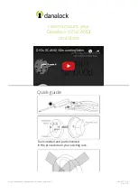
V3 US
Brand: danalock Pages: 3
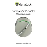
V3 SCANDI
Brand: danalock Pages: 8
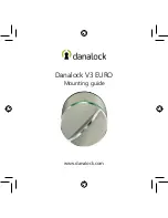
V3 EURO
Brand: danalock Pages: 32
V3 SCANDI
Brand: danalock Pages: 24

V3 SCANDI
Brand: danalock Pages: 20

V3 BT HK SCANDI
Brand: danalock Pages: 17

Danapad V3
Brand: danalock Pages: 13

CM-DL1702
Brand: Comax Pages: 2

200 Strike
Brand: FOLGER ADAM SECURITY Pages: 8

Conexis Smart Lock L2
Brand: Yale Pages: 22

175 Biometric
Brand: MARKS USA Pages: 4

CH 53
Brand: PBB Pages: 2

Ei5 series
Brand: Salto Pages: 4

EL580L
Brand: Abloy Pages: 12

SmartLocker AX SmartIntego
Brand: Simons Voss Technologies Pages: 53

M610
Brand: LEHMANN Pages: 20

Insys 7202
Brand: Wittkopp Pages: 7

K200
Brand: WiTbelt Pages: 2


