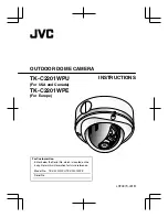
background image

OUTDOOR DOME CAMERA

TK-C2201WPU

(For USA and Canada)

TK-C2201WPE

(For Europe)

INSTRUCTIONS

.

For Customer Use:

Enter below the Serial No. which is located on the 
body. Retain this information for future reference. 

Model No.    TK-C2201WPU,TK-C2201WPE

Serial No.

LST0979-001B

Summary of Contents for LST0979-001B

Page 1: ...PU For USA and Canada TK C2201WPE For Europe INSTRUCTIONS For Customer Use Enter below the Serial No which is located on the body Retain this information for future reference Model No TK C2201WPU TK C2201WPE Serial No LST0979 001B ...

Page 2: ...s 3 Operating Precautions 4 Name of Parts 6 Setup About Connection Cables 10 Setting the Switches 12 Installation Mounting the Camera 13 Adjustment Adjusting Image 23 Adjusting the Auto White Balance 28 Others Specifications 29 Introduction 2 ...

Page 3: ...structure complies with IP66 How to read this manual Conventions and symbols Note Indicates operating precautions Memo Indicates reference data regarding limitations on functions usage and the like A Indicates a reference page or item Contents of this manual v JVC holds the copyright to this manual Any part or all of this manual may not be reproduced without prior consent from the company v Produc...

Page 4: ...t conducted by UL m Maintenance v Clean the dome cover lens using a lens wiper cloth or a tissue For tough stains wipe with a neutral detergent diluted with water followed by wiping with a dry cloth Do not use benzene or thinner to wipe the camera Doing so may melt the surface or cause it to fog m Energy Conservation v When the camera is not in use for a long time turn off the power for safety and...

Page 5: ...malfunction v When this camera is used under high temperatures vertical stripes may appear on the screen This is a characteristic of the CCD and not a malfunction v When this camera is moved from a cold to warm place condensation may occur and the camera may not work In this case leave the camera under room temperature for about one hour before turning on the power v When the power supply voltage ...

Page 6: ...F H I G A Mounting Hole 2 2 A page 14 B Fall Prevention Wire Mounting Screw A page 14 C Conduit Plug Hole side A page 21 D Dome Cover A page 13 E Inner Dome A page 13 F Video signal output connector BNC A page 10 A page 15 Introduction 6 ...

Page 7: ...G Protection Cover A page 15 H Power Supply Cable A page 11 A page 15 I Hole for Connecting Cables Conduit Hole A page 20 J Base A page 19 K Dome Cover Fastening Screw 23 A page 13 Introduction 7 ...

Page 8: ...NOT USED DIPSW SEE INSTRUC TION MANUAL BLC OFF D N AUTO CRT 1 2 3 4 OFF LCD ON F ADJ M N E G I F P Q R S O J K A Focus Adjustment Ring A page 25 B Zoom Adjustment Ring A page 25 C Rotation Knob A page 24 D Fall Prevention Wire To prevent the dome cover from dropping A page 13 E Camera Unit Fastening Screw 22 A page 19 Introduction 8 ...

Page 9: ... Silica Gel A page 16 L Focus Adjust Gear A page 25 M Shooting Direction Mark A page 24 N Pan Center Mark A page 24 O Rotation Center Mark A page 24 P Function Selection Switches A page 12 Q MENU Button Display the menu screen Refer to the attached manual MENU SETTING for more details about setting the menu R Status Indication Lamp Lights up when the power is turned on S J K H I SET Button This al...

Page 10: ...urn off the power of devices before connecting cables To Power Supply To video Signal Cable Memo v Connect to AC 24 V power supply if using the heater sold separately KA ZH215U Video signal cable coaxial cable Connect a 75 K coaxial cable BNC such as RG 59 to the video signal output connecter BNC Setup 10 ...

Page 11: ...m AWG 14 140 m 450 ft 350 m 1100 ft 120 m 390 ft Φ 2 0 mm AWG 12 220 m 720 ft 550 m 1800 ft 180 m 590 ft Note v If thin cables are used the resistance of the cables will be high and a significant voltage drop will occur when the camera is at its maximum power consumption Either use a thick cable with low resistance or place the power supply near to the camera and shorten the length of the cable to...

Page 12: ...en it is dark The image is set to color at all times when OFF is selected Default setting AUTO Memo You can set the image to black and white at all times using the menu TK C2201WPE only 2 BLC OFF ON Backlight Compensation Selector Switch Set this to ON when shooting in backlight The subject becomes easier to see as brightness is adjusted according to the photometry area set in BLC AREA of the menu...

Page 13: ...iling ensure to wear safety glasses to protect the eye from any falling objects Mounting the camera directly to the ceiling or on the wall When mounting to a wall replace areas indicated as ceiling in the procedures by wall m Preparing the camera 1 Remove the dome cover screws x3 2 Remove the inner dome from the catches two locations The inner dome can be easily removed by turning it about 45 degr...

Page 14: ...the fall prevention wire at a structurally strong location 3 Mount the camera unit to the ceiling Pull the cables from the ceiling and camera towards the lens as illustrated in the diagram align the ñ mark to the shooting direction and mount the camera to the ceiling Align the ñ mark upwards when mounting the camera on the wall 2 8 mm 2 mm 1 3 4 1 6 5 mm 30 mm 6 mm and below 12 mm and below 4 mm 2...

Page 15: ...ll isolate and protect the metallic parts of the connectors 2 Connect the power supply cable A page 11 3 Wrap insulation tapes around the connecting parts of the power supply cables Memo Wrapping insulation tapes will improve future work conditions as well as reduce penetration by noise and other objects 4 Wrap the insulation tape 5 Push the connector of the connected coaxial cable back to the cei...

Page 16: ...agram 2 1 Silica gel Lug plate Sealing material Silica gel insertion space This illustration is for the purpose of explanation The camera unit is not shown here Secure the silica gel with the lug plate such that it will not drop Note v When mounting the camera under raining conditions make sure that rain does not enter into the camera v Be sure to use the silica gel provided Failure to do so may f...

Page 17: ...ack when all settings are finished 1 Mount the inner dome Mount the inner dome in a way that supports the tilt direction of the lens Insert the inner depression of the inner dome into the protruding parts beside the fastening screw Push it in until it is fixed by the catches 2 locations Inner dome Catches 2 Protruding part Inner depression Installation 17 ...

Page 18: ...ted before mounting the dome cover v Be sure to secure the dome cover firmly If it is not firmly secured the cover can drop or the humidity inside the camera can increase and fog up the interior of the cover v When the cover is removed again after mounting the dome cover the field angle may changed If the field angle is changed re adjust the focus and the field angle v Ensure that the fall prevent...

Page 19: ...e base and mount the fall prevention wire to the camera unit Loosen the camera unit fastening screw 2 locations with a screwdriver Press the catch 2 locations inwards and remove the camera from the base Remove the fall prevention wire fastening screw on the base to mount the fall prevention wire The fall prevention wire is not provided 1 RE LE AS E 2 2 1 2 1 Base Camera unit Catches x 2 Installati...

Page 20: ...le type of screws according to the material of the mounting location 6 Mount the fall prevention wire to a structurally strong location 3 4 5 6 8mm 2mm M4 mm screw Fall prevention wire 12 mm and below Sealing tape 7 Connect the cables A page 15 Push the connector of the connected coaxial cable back to the pipe 8 Mount the camera unit to the base Push in until the catch 2 locations snaps on Note Ma...

Page 21: ...nd the sealing tape around the pipe junction where the conduit hole thread lines with the pipe screw hole two or more times 4 Remove the conduit plug from the base Loosen the mounting screw M3 x 6 mm using a flathead screwdriver and remove the conduit plug at the side of the base 5 Mount the conduit plug that was removed to the conduit hole at the bottom of the base 6 Mount the base to the pipe Sc...

Page 22: ... unit to the electrical box using the mounting hole 2 locations with the M4 screw 2 pieces Memo The screws are not provided M4 Screw 4 Inch square electrical box 3 The procedures for the following are the same as that for normal camera mounting Connecting the cable A page 15 Process after connection A page 16 Adjusting images A page 23 Mounting the dome cover A page 17 Installation 22 ...

Page 23: ...y touching the metallic part of the monitor terminal before handling the camera as static electricity may cause the camera to malfunction 1 Mount the monitor Connect the monitor terminal of this camera to a monitor to adjust the camera s shooting direction image and focus 2 Turn on the camera 75 Monitor terminal terminal Monitor Adjustment 23 ...

Page 24: ...rection mark pan center mark and rotation center mark Be sure to hold the rotation knob and adjust the rotation without holding the lens unit v Loosen the tilt fastening screw before performing tilt adjustment v After adjusting the field angle tighten and secure the tilt fastening screw so that the field angle will not be misaligned Note v Moving the camera beyond its adjustable range may deterior...

Page 25: ...d in the diagram to disengage the gear Note To prevent the gear shaft from breaking when the gear is opened too far out from B remove the gear shaft from the bearing C in diagram In this case re insert the shaft back into the bearing C and return it to the original position before using Loosen the fastening screw for the focus adjustment ring and move the ring to the left right to adjust the focus...

Page 26: ...the focus adjust mode the electronic shutter will function automatically As a result the screen will appear grainy This is not a malfunction Shoot the subject Return the catch to A in the diagram and then rotate the knob to adjust the focus to the optimum position Rotate the focus adjust gear knob one base pitch in the direction of the arrow in the diagram to correct the focus shift when mounting ...

Page 27: ... of the focus adjustment ring Hold and press the focus adjust gear between your fingers in the direction of the arrows in the diagram and tighten the fastening screw of the focus adjustment ring Focus adjustment ring Adjustment 27 ...

Page 28: ...ITE BALANCE CONTROL E AWC SET R GAIN B GAIN AWC OK WHITE BALANCE CONTROL E AWC SET R GAIN B GAIN 160 160 160 160 SET button MENU button AWC OPERATION during operation AWC OK adjustment completed button m Error display If auto white balance adjustment is not successful the following messages will appear on the monitor AWC ERROR NG Subject error Displayed when there is not enough white color on the ...

Page 29: ...0 Angle of view f 2 8 mm 99 5 7 H 2 73 2 7 V f 10 5 mm 27 4 7 H 2 20 6 7 V Angle adjustment range Pan 5175 7 Tilt 580 7 Rotation 5100 7 Power supply AC 24 V 60 Hz DC 12 V UL Listed Class 2 power supply only TK C2201WPU AC 24 V 50 Hz 60 Hz DC 12 V TK C2201WPE Power current consumption 2 3 W TK C2201WPU 220 mA TK C2201WPE when using heater KA ZH215U 20 W TK C2201WPU 1 A TK C2201WPE Mass approx 1 3 k...

Page 30: ...Specifications Continued Accessories TK C2201WPU WARRANTY CARD 2 1 INSTRUCTIONS 2 3 Silica gel 2 1 Wrench 21 Template 2 1 TK C2201WPE INSTRUCTIONS 2 5 Silica gel 2 1 Wrench 21 Template 2 1 Others 30 ...

Page 31: ...0 6 1 4 9 5 1 4 42 1 5 8 125 4 7 8 160 6 1 4 S R 5 3 7 3 8 Screw for conduit bottom surface side surface TK C2201WPU G3 4 14 UNC TK C2201WPE M25 2 1 8 Specifications and appearance of this camera are subject to change for improvements without notice Others 31 ...

Page 32: ...TK C2201WPU TK C2201WPE OUTDOOR DOME CAMERA Q 2009 Victor Company of Japan Limited LST0979 001B ...

Reviews: