background image

INTRODUCTION

CONTROLS,
INDICATORS AND
CONNECTORS

PREPARATIONS

PREPARATIONS
FOR OPERATION

SETTING AND 
ADJUSTMENTS 
BEFORE SHOOTING

SHOOTING 
OPERATION

PLAYBACK MODE

USING EXTERNAL
COMPONENTS

MENU SCREENS

FEATURES OF THE 
CAMERA SECTION

OTHERS

HD CAMERA RECORDER

INSTRUCTIONS

GY-HD250
GY-HD251

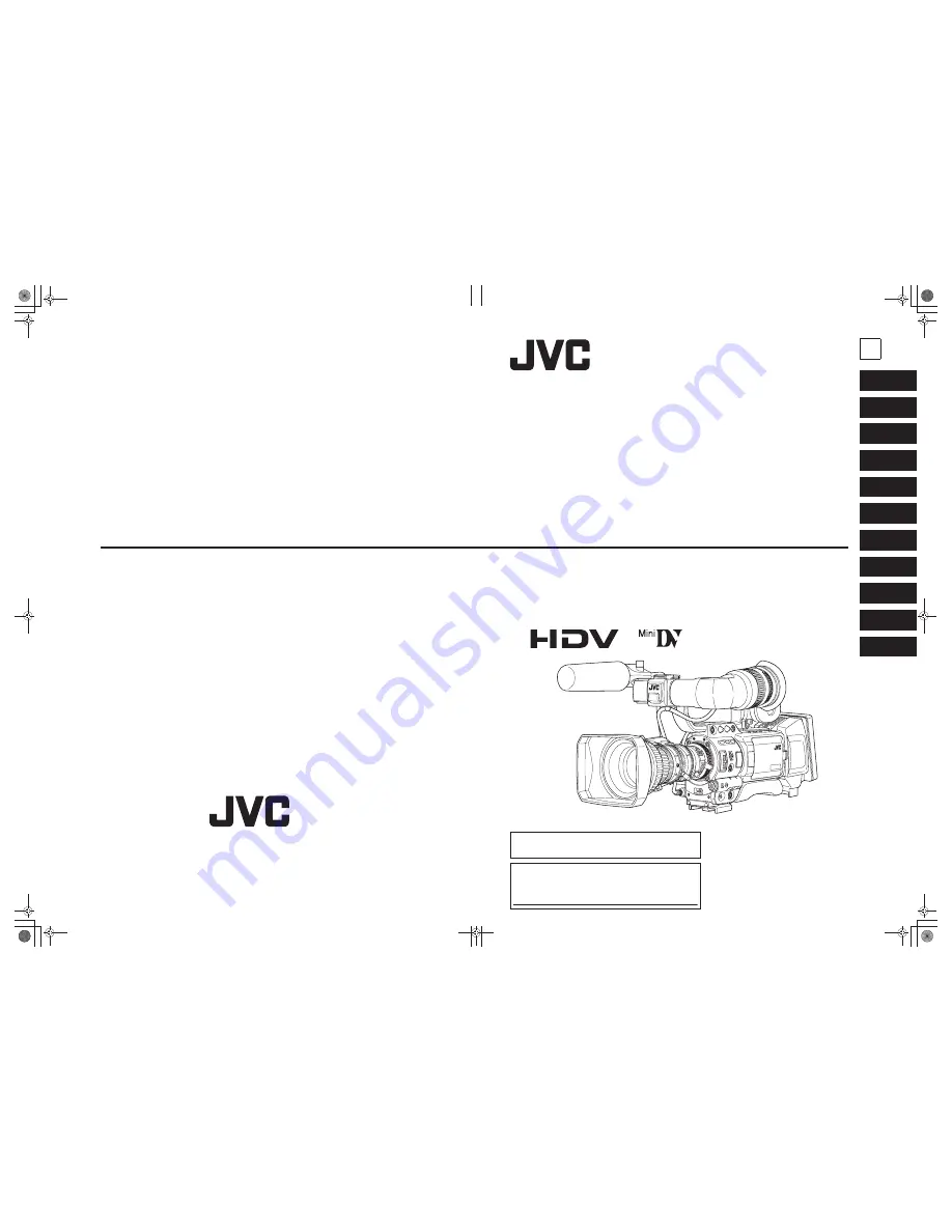
* The illustration shows the GY-HD250/GY-

HD251 HD CAMERA RECORDER with the
provided lens, viewfinder and microphone
attached.

LST0440-001B

E

GY
-HD250/GY

-HD251

  HD
 CAMERA 

RECORDER

Thank you for purchasing this JVC product. Before operating this
device, please read the instructions carefully to ensure the best
possible performance.

For Customer Use:

Enter below the Serial No. which is located on the body.
Retain this information for future reference.
Model No. 
Serial No.

© 2006 Victor Company of Japan, Limited

LST0440-001B

e_hd250_cover_7.fm  Page 1  Tuesday, October 24, 2006  3:13 PM

Содержание GY-HD250U - 3-ccd Prohd Camcorder

Страница 1: ...HD251 HD CAMERA RECORDER with the provided lens viewfinder and microphone attached LST0440 001B E GY HD250 GY HD251 HD CAMERA RECORDER Thank you for purchasing this JVC product Before operating this device please read the instructions carefully to ensure the best possible performance For Customer Use Enter below the Serial No which is located on the body Retain this information for future referenc...

Страница 2: ...an electrician for replacement of the obsolete out let 10 Protect the power cord from being walked on or pinched particularly at plug convenience receptacles and the point where they exit from the apparatus 11 Only use attachments accessories specified by the manufacturer 12 Use only with the cart stand tripod bracket or table specified by the manufacturer or sold with the appa ratus When a cart i...

Страница 3: ... z Consult the dealer or an experienced radio TV technician for help CAUTION CHANGES OR MODIFICATIONS NOT APPROVED BY JVC COULD VOID USER S AUTHORITY TO OPERATE THE EQUIPMENT THIS DEVICE COMPLIES WITH PART 15 OF THE FCC RULES OPERATION IS SUBJECT TO THE FOLLOWING TWO CON DITIONS 1 THIS DEVICE MAY NOT CAUSE HARMFUL INTERFERENCE AND 2 THIS DEVICE MUST ACCEPT ANY INTERFERENCE RECEIVED INCLUDING INTER...

Страница 4: ...HD SD SDI Coaxial Cable 3 m REMOTE Exclusive Cable 5 m STUDIO Exclusive Cable 1 m Dear Customer This apparatus is in conformance with the valid European direc tives and standards regarding electromagnetic compatibility and electrical safety European representative of Victor Company of Japan Limited is JVC Technology Centre Europe GmbH P O Box 10 05 52 61145 Friedberg Germany WARNING TO REDUCE THE ...

Страница 5: ...iate waste handling of this product For more information about collection point and recycling of this product please contact your local municipal office your household waste disposal service or the shop where you purchased the product Penalties may be applicable for incorrect disposal of this waste in accordance with national legislation Business users If you wish to dispose of this product please...

Страница 6: ...ded on this device may appear dis turbed Digital noise may appear during playback due to track ing errors This device records and plays back in the SP mode Recording or playback in the LP mode is not possible In DV format Due to manufacturing dispersion of tapes we recom mend not to record pictures within the first 2 to 3 min utes from the beginning of the tape Before recording important scenes be...

Страница 7: ...output terminal and slave lock function Slave lock to an external time code generator connected to the time code input terminal The time code output terminal outputs built in time code generator data Built in large 3 5 color LCD display In addition to displaying the camera image and the play back image the LCD monitor shows the status screens menu screens for settings and alarm indications Built i...

Страница 8: ...or the Battery Operation 38 Remaining Battery Power Display 38 Operating Time with Battery Pack 38 Precautions for the Battery Pack 38 Recharging 38 PREPARATIONS FOR OPERATION Turning the Power ON 39 Turning the Power ON 39 Turning the Power OFF 39 Loading Unloading the Cassette 40 Cassette Loading 40 Unloading the Cassette 40 Setting and Displaying the Date and Time 41 Setting the Date and Time S...

Страница 9: ...0 CAMERA PROCESS 1 2 Menu Screen 81 CAMERA PROCESS 2 2 Menu Screen 82 ADVANCED PROCESS Menu Screen 83 COLOR MATRIX ADJUST Menu Screen 84 SKIN COLOR ADJUST Menu Screen 84 WHITE BALANCE Menu Screen 85 SWITCH MODE Menu Screen 86 AUDIO MIC 1 2 Menu Screen 87 AUDIO MIC 2 2 Menu Screen 88 LCD VF 1 4 Menu Screen 89 LCD VF 2 4 Menu Screen 90 LCD VF 3 4 Menu Screen 91 LCD VF 4 4 Menu Screen 92 TC UB CLOCK ...

Страница 10: ...ions for transportation Do not drop or hit this device against a hard object Remove the videocassette before transporting this device Do not insert an object other than a videocassette in the cassette insertion slot Be sure to close the cassette cover when this device is not to be used for a long period Do not set the POWER switch to OFF or remove the power cable during recording or playback Other...

Страница 11: ...ding on the operat ing environment and method Therefore the data in the chart should be considered as a reference Time management The accumulated running time of this device can be con firmed with the hour meter display which shows the accu mulated drum and fan motor running time X See How to Display the Hour Meter on page 111 Precautions for Use of Head Cleaning Tape Please use cleaning tape prod...

Страница 12: ... to prevent accidental erasure Slide the switch to SAVE to protect the required recording in the tape from being overwritten To record on the tape slide the switch to REC For recording and storing videotapes in the best con dition Observe the following instructions for the best recording and storage of videotapes Take care of the conditions of handling videotapes It is recommended that you record ...

Страница 13: ... moving this device from one place to another where the temperatures are greatly deferent first remove the vid eocassette place this device in a tightly sealed vinyl bag and then move it to a new environment To ensure no condensation occurs allow the temperature of this device in the bag to reach that of the new environ ment before using it Characteristic CCD Phe nomena Smear and Blooming Due to t...

Страница 14: ...ed adjusting control For adjusting the iris operation speed MEMO If the speed becomes too fast hunting may occur To avoid the phenomena described above perform adjustment again 0FILTER thread Protect the lens with a clear filter or UV filter by screwing the filter onto the thread inside the lens hood from the front Other filters can be used for various effects aZOOM servo connector Connect an opti...

Страница 15: ...80 The luminance level can be changed with the ZEBRA setting in the LCD VF 1 4 menu screen X See page 89 While this switch is pressed to the SKIN AREA side the color tone areas specified with the SKIN COLOR ADJUST item on the ADVANCED PROCESS menu are indicated in the viewfinder The switch returns to the OFF position when released X See How to Use Skin Detail on page 103 The Skin Detail color tone...

Страница 16: ...ume control 3 on page 14 MEMO The volume of the alarm sound is set with the ALARM VR LEVEL item on the OTHERS 1 2 menu screen When using a stereotype jack and stereo sound should be output the following setting should be performed Set the MONITOR SELECT switch d on page 19 to BOTH Set the AUDIO MONITOR item on the AUDIO MIC 2 2 menu screen to STEREO Connecting the Earphone Cable To reduce the emis...

Страница 17: ... power is turned on the mode becomes the Camera mode AUTO The audio level is automatically adjusted according to the input level When excessive audio is input the limiter works to suppress the audio level The AUTO LED in the CH 1 CH 2 AUDIO LEVEL area f on page 15 lights MANU Allows you to adjust the audio levels using the CH 1 CH 2 AUDIO LEVEL volume con trols f on page 15 Set AUDIO LIMITER on th...

Страница 18: ...ions depending upon the subject Set them using the USER1 3 items in the SWITCH MODE menu screen X See page 86 Use this button to preset the time code X See page 46 MEMO The USER buttons work together with the menu settings When a menu screen is being displayed they also func tion as menu operation buttons X See Setting Menu Screens on page 75 9 SHUTTER Shutter Menu dial Every time this dial is pre...

Страница 19: ...ds if you need to turn the power on again e REC REC trigger button start stop recording Start and stop recording using this button This works together with the REC trigger button on the top and the lens VTR trigger button When SPLIT is set for the 1394 REC TRIGGER item on the OTHERS 2 2 menu screen this button becomes the start stop recording button for an external device X See page 97 X See Backu...

Страница 20: ...sertion or removal of the videocassette CAUTION To prevent foreign objects from entering the internal parts of the VTR unit do not leave this device with the cover open for extended periods of time 8 VIDEO OUT Video output terminal RCA This is a terminal for composite video signal output Select whether or not to output a signal with setup in SET UP on the VIDEO FORMAT 2 2 menu screen Only for U mo...

Страница 21: ...ignals in this terminal when externally synchronizing camera images or playback images Synchronization signal BB Black Burst signal of SD or Tri sync signal of HD Input composite video signals to record images from an external device with this device Select the signal to input with the GENLOCK AUX IN switch c X See Using GENLOCK Functions on page 66 X See Recording Composite Video Signals from an ...

Страница 22: ... button on the right panel and the lens VTR trigger button 9 REC LOCK REC LOCK switch Slide this switch in the direction of the arrow to lock the REC trigger button 8 Use this to prevent unwanted recording The REC trigger button on the right panel and the lens VTR trigger button are not locked 0SD memory card cover When you open this cover you can insert and remove the SD memory card X See Inserti...

Страница 23: ...continuously When you release FAS mode all of the settings return to their previous modes CAUTION When the power is turned on while the camera is in the FAS mode it takes about 10 seconds before the automatic adjustment of FAS is completed All of the previous setting contents are recalled when the FAS mode is cancelled h STOP Stop button Press to enter the stop mode i REW Rewind button Press this ...

Страница 24: ...t HD HDV HDV HD60P 720 60p q q q N A N A 480 60i HDV HD30P 720 30p q q 720 60p N A N A 480 60i HDV HD50P 720 50p q q q N A N A 576 50i HDV HD25P 720 25p q q 720 50p N A N A 576 50i HDV HD24P 720 24p q q 720 60p N A N A 480 60i DV U model only DV 60I 480 60i q q q q q q DV 24P 480 60i 24p q q q q q q DV 24PA 480 60i 24p q q q q q q E model only DV 50I 576 50i q q q q q q DV 25P 576 50i 25p q q q q ...

Страница 25: ...omposite Out HDV PB OUTPUT menu item NATIVE 720P 1080I NTSC PAL HDV 720 60p q q q 1080 60i 480 60i N A 480 60i 1 480 60i 1 480 60i 720 30p q 720 60p q 1080 60i 480 60i N A 480 60i 1 480 60i 1 480 60i 720 50p q q q 1080 50i N A 576 50i 576 50i 2 576 50i 2 576 50i 720 25p q 720 50p q 1080 50i N A 576 50i 576 50i 2 576 50i 2 576 50i 720 24p q 720 60p q 1080 60i 480 60i N A 480 60i 1 480 60i 1 480 60i...

Страница 26: ...ATUS button while normal screen is displayed to show one of the status screens The contents of the status display are divided into those for the Camera mode and those for the VTR mode Each time the STATUS button is pressed in the Camera mode one of 5 status screens is displayed STATUS 0 1 2 3 4 One type of screen is displayed in the VTR mode CAMERA MODE display example MEMO When the STATUS button ...

Страница 27: ...SP is set to SEC V SHUTTER 1 24 01 to 1 10489 5 Shutter was turned OFF SHUTTER OFF 1 4 Shutter speed value was changed When SHUTTER DISP is set to DEG SHUTTER 360 0 180 0 172 8 150 0 144 0 135 0 120 0 105 0 90 0 75 0 60 0 45 0 30 0 22 5 11 2 Variable shutter speed value was changed When SHUTTER DISP is set to DEG 0 to 360 White balance value was changed Example WHITE BAL A 3200K Numeric value Any ...

Страница 28: ...ay style are set on the TIME DATE menu LCD BRIGHT indication When the brightness of the monitor screen is adjusted with the LCD BRIGHT button the date and time indications and the VTR mode indication 2 are turned off and the LCD BRIGHT indicator is displayed Example BRIGHT 5 O Numeric value Any of 5 4 3 2 1 0 1 2 3 4 5 4 Indication of Black operation B Displayed when the black stretch or black com...

Страница 29: ...IN terminal Blinks when synchronization is unsuccessful Turns off If there is no input signal 4 Remaining tape indication Remaining tape indication displayed in 1 minute steps This indicator blinks when remaining tape time is equivalent to less than 3 minutes Whether or not to display this item is set with the TAPE REMAIN item on the LCD VF 3 4 menu screen X See page 91 When inserting a brand new ...

Страница 30: ... See AUDIO REF LEVEL on page 87 9 Iris indicator display M Iris set higher than normal b Iris set to normal N Iris set lower than normal The indication can be switched ON OFF with the F NO IRIS IND item on the LCD VF 1 4 menu screen X See page 89 0 Iris F value indication Indicates the F number of the connected lens OPEN F2 F2 8 F4 F5 6 F8 F11 F16 CLOSE It is not displayed when the lens is removed...

Страница 31: ...dB 15dB 18dB ALC SHUTTER When STEP is selected OFF 1 6 1 6 25 1 7 5 1 12 1 12 5 1 15 1 24 1 25 1 30 1 48 1 50 1 60 1 100 1 120 1 250 1 500 1 1000 1 2000 1 4000 1 10000 When VARIABLE is selected 1 24 01 1 10489 5 Displayed when FAS or ALC mode is selected EEI The range for the shutter speed differs depending on the video format X See page 86 WHT BAL A 00K B 00K PRESET 00K FAW MANUAL Only when the r...

Страница 32: ... tape time is not indicated When the tape has been run the indication will appear The remaining tape indication is to be used only as a guide When this device is used at low temperatures it may take a while before the indication of the remaining tape time appears 4 Event display Displays messages related to VTR operations X See pages 106 108 5 Audio sampling frequency in dication The audio samplin...

Страница 33: ...ura battery Voltage remaining capacity 0 Audio Lock indication Displayed when the audio signal from DV recording or playback is locked to the video signal No Item Contents 1 Audio Lock Indicator Displayed during recording and playback when the audio signal is locked to the video signal 2 Time Code Generator Setting Indicator Indicates the set status of the TC GENE switch on the side section FREE T...

Страница 34: ...e the STATUS 2 3 screen is shown the STATUS 0 screen returns to display the alarm X See page 106 When an abnormality occurs in the VTR a warning message with an error code is displayed X See pages 106 108 Safety Zone Indication Camera mode only The indication of the following safety zone and center mark indications can be turned ON OFF with the SAFETY ZONE item and CEN TER MARK item on the LCD VF ...

Страница 35: ...tton does not work When the LCD VF item in the LCD VF 4 4 menu is set to ON the LCD monitor and viewfinder VF displays are as shown below MEMO Press the DISPLAY button for 2 seconds to switch the LCD screen display ON and OFF The viewfinder screen is always displayed SAFETY ZONE 2 35 1CE 2 35 1CH CENTER MARK OFF ON OFF ON DV 60I DV 50I DV 24P DV 24PA DV 25P 4 3 Cannot be selected 16 9 HDV HD60P HD...

Страница 36: ...ZS13B 1 2 Zoom Lens S14 7 3B12U FUJINON S17 6 6BRM FUJINON S20 6 4B12U FUJINON YH16 7K12U CANON YH19 6 7K12U CANON 2 3 Zoom Lens Microphone 1 3 Zoom Lens Th16 5 5BRMU FUJINON Excluding the CHU CHE model GY HD250 GY HD251 Standard Package Mount Converter 1 2r1 3 ACM 12 2 3r1 3 ACM 17 Carrying Case GY HD250 GY HD251 SD Memory Card XLR 4P AC Adapter AC Tripod Dolly Composite Cable RCA pin Audio Cable...

Страница 37: ...ophone holder Place the microphone toward the front to prevent it from interfering with the cassette cover 3 Turn the knob on the microphone holder clockwise to secure the microphone 4 Connect the microphone cable to the INPUT1 or INPUT2 input connector on the GY HD250 GY HD251 5 Attach the microphone cable to the clamp 6 Make sure to perform the correct setting for use of a phantom microphone X S...

Страница 38: ...irection of the arrow CAUTION Be sure not to touch the metal connector area of the SD memory card 3 Close the SD memory card cover Taking out the SD memory card 1 Push the SD memory card in the direction of the arrow The SD memory card comes out slightly 2 Pull the SD memory card straight out About SD Memory Cards When you use an SD memory card that was either just purchased or formatted on a devi...

Страница 39: ...ip of this device as it clicks into place CAUTION The front base mount may be locked while the pin of the tripod base is not inserted into the hole on the rear base mount of this device Therefore after mounting make sure that these parts are engaged properly When moving this device mounted on a tripod any impact or vibration should be avoided as this may cause this device to become detached and to...

Страница 40: ...in battery is constantly being charge whenever the GY HD250 GY HD251 is connected to a power supply but it gradually discharges while the GY HD250 GY HD251 is dis connected from a power supply The battery will be fully dis charged when the GY HD250 GY HD251 is not used for about three months in which case the set date and time and time code data are reset In this case recharge the built in battery...

Страница 41: ...ntil it clicks The battery is attached Removing the Battery Slide the battery towards you LCD screen side panel while holding down the release lever and pull away from the device to remove the battery GY HD251E Use an IDX Endura battery Attaching the Battery 1 Face the battery terminals down and align the battery V mount with the battery adapter V mount attachment 2 Slide the battery down until it...

Страница 42: ...e 91 Operating Time with Battery Pack When a fully charged battery pack is attached the approxi mate continuous operating time is as follows Battery operating time may differ depending on the age of the battery pack charging conditions and the operating environment etc Use the values in the table on the above for approximate reference times Operating time is reduced in areas with a cold environ me...

Страница 43: ...GY HD251 enters the stop mode STOP is displayed in the VTR operation mode indication area of the LCD monitor and or in the viewfinder HDV DV input is possible through the IEEE1394 connector Turning the Power OFF 1 Place the GY HD250 GY HD251 in the record standby or STOP mode 2 Set the POWER switch to OFF 3 Remove the battery pack or the power supply to the DC INPUT connector When the camera is no...

Страница 44: ...he videocassette cover opens completely The LED next to the EJECT switch flashes A few seconds pass before the videocassette tape is ejected 3 The LED turns off and the videocassette cover opens Take out the videocassette tape 4 Carefully push the center of the videocassette cover in the direction of the arrow as far as it will go to close it CAUTION When you close the videocassette cover push it ...

Страница 45: ...appears Set the DISPLAY item on the TIME DATE menu screen to ON 5 Make settings on the TIME DATE menu screen This includes display style etc 1Rotate the SHUTTER dial to align the cursor K with the item to be set and then press the SHUTTER dial The setting area of the selected item starts blinking 2Rotate the SHUTTER dial to change the setting and then press the SHUTTER dial The setting area stops ...

Страница 46: ...r or not the time and date should be displayed on the screen and how to display them are set on the TIME DATE menu screen 1 Display the TIME DATE menu screen 1Select the TC UB CLOCK item on the TOP MENU screen 2Select the TIME DATE item on the TC UB CLOCK menu screen 2 Set the TIME DATE menu screen Display of date and time in the various operation modes TIME DATE menu screen Date Time Hour Min CLO...

Страница 47: ...or Pressing the STOP button for 1 second in the EJECT or stop mode displays the DV input time code data or user s bit data from the IEEE1394 connector on the STATUS screen To return to display of the original time code or user s bit press the STOP button Display of the normal time code or user s bit is also restored by performing VTR operation MEMO To use input time code data from the IEEE1394 ter...

Страница 48: ...d is approximately 29 97 frames but per time code 30 frames are processed To compensate for this differ ence the mode called drop mode drops frame 00 and 01 for every minute not divisible by 10 The non drop frame mode is when no frames are dropped and the actual time shift neglected TC UB CLOCK menu screen FRAME RATE 50 25 Whether or not user s bit data should be recorded can be selected with the ...

Страница 49: ... K with the PAGE BACK item and then press the SHUTTER dial to return to the TOP MENU screen Presetting user s bit data The user s bit data are preset with the UB PRESET item on the TC UB CLOCK menu screen The method for setting is the same as the method for setting the time code described on the left The user s bit can be specified using numerals or alpha betic letters from 0 to F for each digit T...

Страница 50: ... minute second and frame The blinking digit can be set 1Turn the SHUTTER dial to change the value of the blinking digit Turn the SHUTTER dial up to increase the value and down to decrease the value 2Press the SHUTTER dial to change the blinking digit 3Repeat steps 1 and 2 and continue setting for each row 4 Press the USER3 button to confirm the setting data The LCD screen returns to the original s...

Страница 51: ...time code or user s bit data recorded on the tape is dis played on the LCD screen or viewfinder status screen When the PB PR TC switch is set to TC the playback time code is output from the PB TC OUT terminal Only in VTR mode When HD SD SDI OUT of the VIDEO FORMAT 2 2 menu screen is set to ON the playback time code is output from the HD SD SDI terminal MEMO During playback if a portion of tape wit...

Страница 52: ...en status is in magnified size characters are displayed 8 Press the USER1 button to begin slave lock To skip slave lock press the USER3 button and clear the status display 9 Check that the time code that is synchronized with the master unit is running 10 Disconnect the IEEE1394 cable 11 The slave unit finally returns to Camera mode MEMO Slave lock cannot be performed in the following instances Sla...

Страница 53: ... data L lights up in the STATUS 1 screen of LCD screen or viewfinder L also lights up when the LCD screen is in enlarged character display L blinks when the time code cannot be synchronized 2 The built in time code generator continues to run even if the external time code generator is disconnected after synchronization CAUTION If a time code generator is connected or disconnected during recording ...

Страница 54: ...black and white display Viewfinder Adjustment Direction of the Viewfinder Adjust the position and angle of the viewfinder Diopter Adjustment Rotate the eyepiece focusing ring until the viewfinder screen image is clearly visible Adjustment of the Viewfinder Screen PEAKING Adjusts the contour of the LCD monitor and the viewfinder screen VF BRIGHT Adjusts the brightness of the viewfinder screen Adjus...

Страница 55: ...f the illumination is too strong reduce it or move to a darker place 4 Turn the zoom lever until the lens is at the maximum tele photo position 5 Bring the subject into focus 6 Set the lens to maximum wide angle 7 Loosen the back focus ring retaining knob 8 View the same subject and adjust the back focus ring for the best possible focus 9 Repeat steps 4 through 8 about three times for fine adjustm...

Страница 56: ...ilter or use another white object and re adjust the white balance ERROR LOW LIGHT Insufficient illumination Displayed when the illumination is dim Increase the illumi nation and then re adjust the white balance ERROR OVER LIGHT Excessive illumination Displayed when the light is excessively bright Decrease the illumination and then re adjust the white balance CAUTION Do not adjust using any highly ...

Страница 57: ...ERA PROCESS 1 2 rCAMERA PRO CESS 2 2 rADVANCE PROCESSrWHITE BALANCE Setting in the WHITE BALANCE screen is performed as fol lows Selecting an item Turn the SHUTTER dial to align the cursor j with the desired item and press the SHUTTER dial The item is selected and the setting value blinks Changing the setting value Turn the SHUTTER dial to change the blinking value When the SHUTTER dial is pressed...

Страница 58: ...ange the setting and push the SHUTTER dial The setting stops flashing and is temporarily set Move the cursor K to the EXECUTE item and EXE CUTE flashes 5 Push the SHUTTER dial REBOOT SYSTEM CHANGE is displayed on the screen and after a few seconds the system is reboo ted Setting the REC Item Set the REC item using the same steps as for the FRAME RATE item MEMO If you change the FRAME RATE item set...

Страница 59: ...s displayed If the above applies you can set to display the image in the style of 4 3 televisions X See DOWN CON HDV on page 78 In the SAFETY ZONE item on the LCD VF 1 4 menu screen you can display the safety zone for a standard screen as well as a 16 9 screen in the viewfinder or LCD monitor X See page 89 When the ASPECT item is set to 4 3 the screen that is displayed may differ depending on the ...

Страница 60: ...he audio input level control The audio input level can be adjusted manually when the GY HD250 GY HD251 is in the record record standby or stop mode 1 Set the CH 1 CH 2 AUDIO SELECT switch of the chan nel whose audio level that you want to adjust manually to MANU 2 Rotate the audio input level control corresponding to the audio input level to be adjusted Adjust so that the peak level does not excee...

Страница 61: ... can be monitored through the monitoring speaker or earphone Select the audio channel to be monitored using the MONI TOR SELECT switch The MONITOR volume control adjusts the monitoring vol ume The loudspeaker or earphone outputs an alarm tone in the case of an abnormal condition occurring in this device An alarm tone is also output when the tape end is reached or when the battery is running down D...

Страница 62: ...ended before recording important events to confirm the recording is satisfactory The microphone may pick up the sound of the lens iris if the iris is changed abruptly or the iris is manually moved abruptly during recording About the Focus Assist Function When you press this button during shooting the area of focus is displayed in blue red or green making it easy to focus accurately X See LCD VF 1 ...

Страница 63: ...t 7 seconds when the content was recorded in HDV format can be played back The recorded contents can be checked on the LCD moni tor in the viewfinder or on a monitor connected to the video signal output connectors 1 In the record standby mode press the RET button on the camera lens section The tape rewinds and about 6 seconds of the content recorded in DV format is played back and about 8 sec onds...

Страница 64: ...me code ZERO PRESET Resets all time codes to zero 0 CANCEL Clears the set time code The frame mode is set depending on the setting in the DROP FRAME item on the TC UB CLOCK menu screen The time code value at the point when the Record Standby mode is engaged may differ some frames from the value set for this item UB DATA Sets the user s bits of the HEADER REC section EXECUTE Confirms the set user s...

Страница 65: ...de is engaged automatically During HEADER REC recording HEADER REC is shown blinking on the LCD monitor and in the view finder The menu screen is not displayed during HEADER REC recording 3 After HEADER REC recording is completed and the Record Standby mode is engaged normal recording starts when you press the REC VTR trigger button When the TC GENE switch is set to either REC or REGEN the time co...

Страница 66: ...tape that was recorded on another unit digital noise may appear during playback Following loading of the tape the built in head cleaner will emit a sound while operating This does not indicate a malfunction The data recorded for the date and time or time code on the tape can be shown on the screen To enable or dis able the display is selected on the menu screen Fast Forward Rewind Press the FF but...

Страница 67: ...hannels the PB AUDIO CH DV item on the AUDIO menu screen must be set After recording on the CH 3 and CH 4 channels is not possible The PB AUDIO CH DV item is also valid for embedded audio The sampling frequency for embedded audio is 48 kHz USER 3 USER 2 USER 1 STATUS MENU 2 1 ND FILTER REC OFF ON POWER WHT BAL AUTO AUDIO LEVEL AUTO CH 1 CH 2 VF BRIGHT CH 2 CH 1 AUDIO SELECT MANU AUTO TC LCD BRIGHT...

Страница 68: ...both devices OFF and connect the IEEE1394 cable Do not insert incorrectly in reverse the IEEE1394 cable end to IEEE1394 port of both devices Do not connect the IEEE1394 cable under the condition of static electricity Turn the power of both devices OFF when changing the IEEE1394 switch from to HDV DV Displaying Alarms CHANGE 1394 SWITCH Displayed when the setting for the input output video format f...

Страница 69: ... for U model ON Set to this when input analog signals include the setup signal OFF Set to this when input analog signals do not include the setup signal Operation Start and stop recording with the REC VTR trigger button EE images of input signals are output in DV 60I U model or DV 50I E model formats from the various image output terminals CAUTION Recording cannot be checked using the lens RET but...

Страница 70: ...o nization signals SYNC LOCKING is displayed on the screen When locking to external synchronization sig nals is complete the indication disappears and you can enter recording mode Synchronized Signals The synchronized signal differs depending on the input sync signal Refer the table below SC Subcarrier phase H Horizontal phase V Vertical phase F Field phase Adjust SC PHASE and H PHASE in the above...

Страница 71: ...utput image signals of the Y PB PR terminal Only for DV format 5 Set the audio output X See page 63 Set the AUDIO menu screen X See page 87 PB AUDIO CH DV item Set the audio channel to be output 6 Insert the videocassettes 7 Press the PLAY STILL button on the GY HD250 GY HD251 to start playback 8 Start recording on the recording unit For details see the instructions to the unit used for recording ...

Страница 72: ...a tion 9 When dubbing is finished stop recording on the record ing device press the STOP button on this device and stop the playback MEMO Switch the IEEE1394 switch when this device is OFF When you dub still images they are low resolution images Noise may also enter the audio Operations may differ depending on the features and specifications of the connected device and operations or data exchange ...

Страница 73: ... from the playback unit appears on the GY HD250 GY HD251 s LCD monitor and view finder screen 9 Press the REC VTR trigger button on the GY HD250 GY HD251 to start recording To temporarily pause the recording press the REC or VTR trigger button To restart the recording press the REC or VTR trigger button again 10 When dubbing is completed Press the REC VTR trigger button or the STOP button on the G...

Страница 74: ...his device inter rupting the backup recording image Operation Start and stop of recording on the backup unit takes place in accordance with the operation of the REC VTR trigger button on the master unit Depending on the GY HD250 GY HD251 or the backup unit the image audio and or time code may deviate from what they should be at the points where the recording is started or stopped MEMO When the bac...

Страница 75: ... Shutter Speed in 24p Mode When this device is in 24p mode shutter speed cannot be set to 1 60 U model or 1 50 E model with the remote control unit Even if shutter speed is set to 1 60 or 1 50 with the remote control unit when in 24p mode the shutter speed for the device is 1 48 When H PHASE adjustment is performed with the remote control unit only H PHASE of SD signal operates When adjusting H PH...

Страница 76: ...CE R B LEVEL G PAINT R B LEVEL q G GAIN 0dB q G 6dB q G 9dB q G 12dB q G LOLUX X 3dB X 6dB X ALC EEI q G ALC q X NEGA OFF ON X SHUTTER NORMAL q G 1 100 q G 1 1 120 q G 2 1 250 q G 1 500 q G 1 1000 q G 1 2000 q G 1 4000 G 1 10000 G EEI q X V SCAN X ZOOM q X FOCUS q X HI RESO OFF ON X MASTER BLACK LEVEL q G GAMMA OFF ON X GAMMA MASTER LEVEL X KNEE MASTER LEVEL X TITLE OFF ON X TITLE POSITION X TITLE...

Страница 77: ...r purpose The items on the menu screens differ with the Camera mode and the VTR mode The contents of set items are stored in the GY HD250 GY HD251 s memory and are retained even when the power is turned off The FILE MANAGE menu screen can be used to store the menu setting contents on the GY HD250 GY HD251 or SD memory card Camera Mode TOP MENU screen CAM e_hd250 book Page 73 Tuesday October 24 200...

Страница 78: ...MENU SCREENS 74 Menu Screen Configuration Cont d VTR Mode IEEE1394 Input Mode TOP MENU screen VTR e_hd250 book Page 74 Tuesday October 24 2006 3 11 PM ...

Страница 79: ... repeat the procedures in steps 5 and 6 above 7 Return to the TOP MENU screen Rotate the SHUTTER dial to align the cursor K with the PAGE BACK item and then press the SHUTTER dial To change settings on other menu screens repeat the procedures in steps 4 to 7 above To save the set contents in FILE select the FILE MAN AGE menu screen and perform the operations for saving to file X See FILE MANAGE Me...

Страница 80: ...onsists of two screens VTR mode It consists of one screen In VTR mode the screen changes to the AUDIO menu screen The cursor K does not move to this item when this device is recording LCD VF Displays a menu screen for selecting whether to display characters on the LCD monitor or in the viewfinder and for adjustments of the picture quality of LCD monitor Camera mode It consists of four screens VTR ...

Страница 81: ...50i signals are output from the VIDEO OUT terminal ON OFF is set when the SHUTTER dial is pressed MEMO Tape recording and IEEE1394 output are not available when this is ON REC item cannot be set when this is ON The cursor is positioned on 1080I CAMERA in the VIDEO FORMAT 1 2 menu screen when this is ON When the FRAME RATE is set to 24 this is fixed to OFF REC Sets the video format for shooting Can...

Страница 82: ...nge This item is also applied to EE images when HDV signals are input to the IEEE1394 terminal Fixed at NATIVE during DV recorded tape playback or DV signal input DOWN CON HDV Set the style to display down converted images in aspect ratio 4 3 SQUEEZE Image that is squeezed horizontally is displayed LETTER Wide image with the top and bottom blackened is displayed MEMO This setting is only valid in ...

Страница 83: ...Outputs analog RGB signals Y C Outputs YC separate signals Signals are output from terminals as shown in the table below depending on the settings When the PBPR TC switch is set to PBPR MEMO SYNC signals are added to all channels for RGB signals In HDV format signals are output in analog component format regardless of these settings SET UP Selects whether to add a setup signal to the video signal ...

Страница 84: ...for light sources with a low color temperature such as halogen lamps 5600K Sets the basic color temperature to 5600K Use for light sources with a high color temperature such as sunlight MEMO This item does not function when the FAW item on the SWITCH MODE menu screen is set to PRESET SMOOTH TRANS 1 Smoothens the transition when the GAIN switch b on page 15 or WHT BAL switch c on page 15 is switche...

Страница 85: ...horizontal contour compensation frequency for the contours details Set this as appropriate for the subject LOW Enhances low frequency bands Use this when shooting subjects with large patterns MIDDLE Enhances middle frequency bands HIGH Enhances high frequency bands Use this when shooting subjects with small patterns V FREQUENCY 1 Use this when shooting subjects with finely detailed patterns Change...

Страница 86: ...UTO is displayed and this cannot be selected REVERSE PICTURE When the lens image is inverted and flipped set ROTATE to record properly OFF No inversion ROTATE Invert lens image MEMO When the REVERSE PICTURE item is set to ROTATE skin detail function is available but the detection area is not displayed in the viewfinder or LCD screen DNR Selects whether or not to set the noise reduction The DNR Dig...

Страница 87: ...a TV screen FILM OUT Sets to a setting for recording onto film MEMO When this item is set to OFF is displayed for the LEVEL item and it cannot be selected LEVEL When STANDARD CINEMA or FILM OUT is set for the GAMMA item a gamma curve can be set individually Increase the number Enhances the tonality of the black However the tonality in the bright areas deteriorates Decrease the number Enhances the ...

Страница 88: ...s MIN 5 4 NORMAL 0 4 MAX 5 B GAIN For manually adjusting the shading of the B axis of the color matrix blue and yellow Increase the number Enhances blue and yellow Decrease the number Reduces blue and yellow Settings MIN 5 4 NORMAL 0 4 MAX 5 B ROTATION For manually adjusting the color phase of the B axis of the color matrix blue and yellow Increase the number Increases reddishness of blue color an...

Страница 89: ... readjust the white balance WHITE PAINT B becomes NORMAL SHADING Adjusts white shading PRESET No white shading adjustment MANUAL Enables white shading adjustment X See White Shading Adjustment on page 53 MEMO When the SHADING item is set to PRESET the LEVEL R LEVEL G and LEVEL B items cannot be selected LEVEL R When the SHADING item is set to MANUAL adjusts the reds of white shading Increase the n...

Страница 90: ... if there is not RET button on the lens you are using RET Functions as a normal RET button FOCUS ASSIST Functions as the FOCUS ASSIST button PAGE BACK When the cursor is in this position press the SHUTTER dial to return to the TOP MENU screen REC Item Setting for STEP Setting for VARIABLE DV 60I HDV HD60P HDV HD30P 1 7 5 1 15 1 30 1 60 1 100 1 250 1 500 1 1000 1 2000 1 4000 1 10000 1 30 03 1 10489...

Страница 91: ...e reference audio input level for the INPUT1 connector When the AUDIO INPUT switch 3 on page 16 is set to MIC or MIC 48 50dB Sets the reference audio input level at 50 dB 60dB Sets the reference audio input level at 60 dB INPUT2 MIC REF Sets the reference audio input level for the INPUT2 connector When the AUDIO INPUT switch 3 on page 16 is set to MIC or MIC 48 50dB Sets the reference audio input ...

Страница 92: ...H 1 CH 2 AUDIO SELECT switch on page 13 X See g FULL AUTO switch on page 19 SEARCH AUDIO DV Selects whether to output audio when searching a tape recorded in DV format This also includes slow playback ON Audio is output OFF Audio is not output PB AUDIO CH DV Selects which channel audio to output when playing back a DV tape with the audio signal recorded in 4 channels Can only be set in VTR mode CH...

Страница 93: ...FF Not displayed 4 3 4 3 zone is displayed 14 9 14 9 zone is displayed 16 9 16 9 zone is displayed 16 9 4 3 16 9 zone and 4 3 zone are display mixed This cannot be selected when DV format is set 2 35 1 CE Displays 2 35 1 zone in the middle of the screen Only in HDV format or 24P or 25P mode 2 35 1 CH Displays 2 35 1 zone at the top of the screen Only in HDV format or 24P or 25P mode CENTER MARK 1 ...

Страница 94: ...ayed NORMAL MIRROR is set when the SHUTTER dial is pressed MEMO MIRROR setting is disabled when color bar is displayed or status is in magnified size X See Outputting Color Bars on page 105 X See Magnified Status Indications on the LCD Monitor on page 29 NEXT PAGE When you display the LCD VF 3 4 menu screen move the cursor to this position and press the SHUTTER dial PAGE BACK When the cursor is in...

Страница 95: ... the viewfinder screen In camera mode only displayed when in STATUS 1 screen VOLTAGE Indicates battery voltage in 0 1 V steps V CAPA Remaining battery is shown in percentage TIME Remaining battery is shown in minutes min VOLTAGE and CAPA can be selected when using an IDX Endura battery When TIME is set VOLTAGE is dis played MEMO When TIME or CAPA is selected the battery indicator displayed before ...

Страница 96: ...ITE Composite signals MEMO Set this to RGB when using the supplied viewfinder The supplied viewfinder will not function properly when set to another setting When this is set to Y or COMPOSITE in the HDV mode images are not output from the Y PB PR terminal When the VF P400 viewfinder sold separately is connected to the Viewfinder connector set this to Y to view HDV format images with the VF P400 Wh...

Страница 97: ...REC item is set to OFF is displayed and this cannot be selected DROP FRAME 1 Selects whether the time code generator framing mode is drop frame or non drop frame DROP Internal time code generator works in drop frame mode Set this when the recorded time is im portant NON DROP Internal time code generator works in non drop frame mode Set this when the number of frames is important UB REC 2 To select...

Страница 98: ... item on the TC UB CLOCK menu screen The time code value at the point when the Record Standby mode is engaged may differ some frames from the val ue set for this item UB DATA Sets the user s bits of the HEADER REC section EXECUTE Confirms the set user s bits ZERO PRESET Resets all user s bits data to 0 CANCEL Clears the set user s bits MEMO The user s bits for the normal recording section are set ...

Страница 99: ...date display YY MM DD Displayed in the format of year month date MM DD YY Displayed in the format of month date year DD MM YY Displayed in the format of date month year Variation Range U model MM DD YY E model DD MM YY When the DISPLAY item is set to OFF is indicated and this item cannot be selected TIME STYLE Selects the style for the time display 24 HOUR Displays the time using the 24 hour syste...

Страница 100: ...clogging and tape damage ALARM VR LEVEL Selects whether or not alarm sound is emitted and the volume of the alarm sound The alarm sound is output through the monitoring loudspeaker and the PHONES jack OFF Sound is not output LOW Alarm sound is soft MIDDLE Alarm sound is normal HIGH Alarm sound is loud FRONT TALLY Selects the lighting method of the FRONT TALLY lamp during recording BLINK The lamp b...

Страница 101: ...ck space and pre roll time when the camera is connected to an external HDD or external back up Recorder via IEEE1394 in HDV mode P 1394 Priority for IEEE1394 recording Auto setting P TAPE Priority for camera VCR recording Note 1 REC start signal will be sent 3 seconds after pressing REC trigger button Actual recording start time is depending on recorder performance Note 2 REC start signal will be ...

Страница 102: ...HD100 power appears on the LCD monitor for 7 seconds MENU ALL RESET Selects whether to reset the menu screen settings to initial settings The camera mode and VTR mode menu settings are reset The TC PRESET UB PRESET and CLOCK ADJUST settings are not reset CANCEL The settings are not reset EXECUTE The settings are reset MEMO The cursor K does not move to this item when the VTR is activated If the cu...

Страница 103: ...y adjusted in HD H PHASE item Increase the number Proceed horizontal phase Decrease the number Delay horizontal phase Settings MIN 1023 to 1 0 1 to 1022 MAX MEMO When adjusting the HD H PHASE the setting value quickly changes while the USER1 or USER2 button is held down for approximately two seconds SC COARSE 1 Adjusts the phase of the subcarrier SC of the composite or YC separate signal of this d...

Страница 104: ... the normal screen Press the SHUTTER dial Return to the FILE MAN AGE menu screen To exit the FILE MANAGE screen Move the cursor K to PAGE BACK and press the SHUT TER dial or press the STATUS button Displaying the FILE MANAGE menu screen Select the FILE MANAGE item on the TOP MENU screen Loading a menu settings file Select the LOAD FILE item on the FILE MANAGE menu screen 1 Turn the SHUTTER dial br...

Страница 105: ... exists OVERWRITE flashes 6 With EXECUTE selected turn the SHUTTER dial to save the menu settings to the selected file Error displays NO CARD No SD memory card is inserted Insert an SD memory card NO FORMAT The SD memory card is not initialized formatted Initialize format the SD memory card NO ACCESS There is a problem with the SD memory card Replace the SD memory card WRITE PROTECT The SD memory ...

Страница 106: ...evice turns off automatically and then turns on When this happens the SUB NAME initial value SCENE is displayed MEMO Even if CAM1 CAM2 CAM3 or CAM4 are reset the cur rent settings are not reset To reset the currently set values select CURRENT Initializing formatting an SD mem ory card Before initializing formatting a card 1Insert and remove the SD memory card with the power to this device OFF 2Dis...

Страница 107: ...rea for the skin detail function The color within the detection area is recognized as the color that the skin detail function will use If the color within the detection area is not recognized as the color that the skin detail function will use ERROR is displayed on the screen 5 If you want to change the range of colors recognized with the skin color detection function follow the steps below 1Turn ...

Страница 108: ...nfirming the color tone area adjusted with the Skin Detail function When you push the ZEBRA switch on the front panel to SKIN AREA the skin detail function turns ON and the color area adjusted with the skin detail function is displayed in color in the LCD monitor or viewfinder MEMO When the REVERSE PICTURE item in the CAMERA PROCESS 2 2 menu screen is set to ROTATE skin detail function is availabl...

Страница 109: ...1 2 or 3 buttons X See SWITCH MODE Menu Screen on page 86 3 Press the USER button to which BARS was assigned Color bars are output MEMO You can select whether to output an audio test signal during color bar output using the TEST TONE item on the AUDIO MIC 1 2 menu screen X See page 87 Color bars are not output when FULL AUTO mode is ON or in VTR mode NTSC standard Outputs color bars compliant with...

Страница 110: ...put and REC trigger button is pressed while SYNC LOCKING is dis played INVALID SYNC Displays when the FRAME RATE item is set to 60 30 or 24 and signals not supported by GENLOCK are input Displays when the FRAME RATE item is set to 50 25 and signals not supported by GENLOCK are input Input supported external synchronization signals X See page 66 DV 60I INVALID DV 24P INVALID DV 24PA INVALID A tape ...

Страница 111: ...DE Tried to use the FF or REW button in camera mode Press the CAM VTR button to set VTR mode HEAD CLEANING REQUIRED Displayed when the video head is dirty Head clogging was detected during an edit search in shooting mode as well as during playback and displayed Clean with a special head cleaning tape X See page 7 CLEANING TAPE Displayed when a head cleaning tape is inserted The display disappears ...

Страница 112: ... the EJECT button to take out the cassette If the tape runs out during recording switch the power OFF and then switch it back ON press the EJECT button and then take out the cassette 5702 TAPE END DET ERROR Tape end sensor error Operation stops All opera tions are rejected Switch the power OFF and then switch it back ON However the tape may be damaged depending on the circum stances Please consult...

Страница 113: ...nds appear as shown in the following table Blinking Pattern Remaining Battery Tape Slow blinking once per sec Remaining battery power is low Remaining tape time is equivalent to less than 3 minutes Fast blinking four times per sec Tape has run out Irregularity has occurred in the VTR Alarm Indications on LCD Monitor Viewfinder Screen TALLY lamp Alarm Sound Condition VTR alarm indication Example I ...

Страница 114: ...t correctly Noise interferes with playback video Video head may be clogged with dirt Clean head with the special head clean ing tape X See Precautions for Use of Head Cleaning Tape on page 7 Sound is not output during playback Is the AUDIO SELECT item on the AUDIO menu screen set to CH3 4 To output the sound of the recording set to CH1 2 Noise appears when playing back a tape recorded on another u...

Страница 115: ...ess the SHUTTER dial The OTHERS 1 2 menu screen is displayed 4 Select the NEXT PAGE item on the OTHERS 1 2 menu screen and press the SHUTTER dial The OTHERS 2 2 menu screen is displayed OTHERS 2 2 Menu Screen 5 To return to the normal screen display do one of the fol lowing Press the STATUS button or Return to the TOP MENU screen select the EXIT item on the TOP MENU screen and press the SHUTTER di...

Страница 116: ...p 480 60i U model 576 25p 576 50i E model Video Format HDV Video signal record ing format HDV720p format 8 bit 19 7 Mbps Compression MPEG 2 video profile level MP H 14 DV Video signal record ing format DV format 8 bit 25 Mbps Compression DV compression 4 1 1 NTSC 4 2 0 PAL Audio HDV Audio signal record ing format MPEG1 Audio Layer II DV Audio signal record ing format 16 bit locked audio 48 kHz PCM...

Страница 117: ...cifications are subject to change without notice Lens 1 Excluding the CHU CHE model Microphone 1 Core Filter 1 Clamp Filter 4 SD memory card 1 Tripod base 1 U model only Instruction Manual 1 Warranty Card 1 USA and Canada only unit mm e_hd250 book Page 113 Tuesday October 24 2006 3 11 PM ...

Отзывы: