JUKI LZ-2280A Series, Instruction Manual
The JUKI LZ-2280A Series is a high-performance sewing machine that guarantees precision and efficiency. Seamstresses and tailors can easily master its features with the accompanying Instruction Manual, available for free download at manualshive.com. Unlock the full potential of this exceptional product by exploring its detailed manual today.
Share
Download


Reviews:
No comments
Related manuals for LZ-2280A Series

9002D
Brand: Janome Pages: 88
Colibri
Brand: N&W Global Vending Pages: 23

40-0100B
Brand: Stamina Pages: 15

MF 3175
Brand: Sagem Pages: 44

206RBL
Brand: Consew Pages: 26

DocuBind P100
Brand: GBC Pages: 1
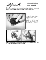
Bobbin Winder
Brand: Gammill Pages: 3

Sfera 6-36 R/F
Brand: Necta Pages: 19

Melodia Classic
Brand: N&W Global Vending Pages: 68

KORI NTO FB
Brand: N&W Global Vending Pages: 38

Genie 353
Brand: Singer Pages: 56

AMS-210EN Series
Brand: JUKI Pages: 249

Premium Stringer 7600
Brand: PENTA Pages: 13

Canto LB 3600
Brand: N&W Global Vending Pages: 72

Hurricane 400 Eco
Brand: Dustbane Pages: 25

Integra-D 19936
Brand: Dustbane Pages: 28

838
Brand: DURKOPP ADLER Pages: 36

867
Brand: Dürkopp Adler Pages: 20


