


User’s Manual
1
User’s Manual
PMI-3110
Ver, A1.2
Date,23rd,Nov.,2015
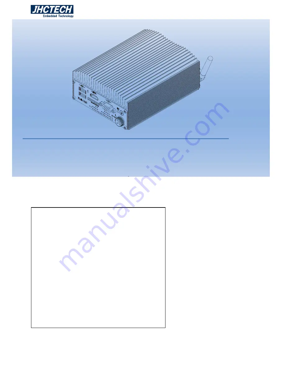
PMI-3110
1, Aluminum case , Fanless disign;
2, Intel® Celeron® J1900;
3, 1xDDR3L-1333 DIMM, max 8GB;
4, 1xmSATA, 1x2.5inch HDD;
5, 1xminipcie with SIM card support 3G/LTE;
6, DC 12V input
;
7, VGA&HDMI display;
8, 2COM/2USB/Audio;
9, 2×Intel I210IT Gigabit Ethernet
;
10, HDD Anti-vibration design
。
Summary of Contents for PMI-3110
Page 8: ...User s Manual 1 General Information CHAPTER 1 ...
Page 11: ...User s Manual 4 PMI 3110 S002 Dimensions Figure 1 1 ...
Page 12: ...User s Manual 5 Hardware Installation CHAPTER 2 ...
Page 14: ...User s Manual 7 Figure 2 3 ...
Page 23: ...User s Manual 16 BIOS Setup CHAPTER 3 ...
Page 38: ...User s Manual 31 Driver Installation CHAPTER 4 ...


