JGR PDL 5, User Manual
The JGR PDL 5 User Manual is a comprehensive guide designed to assist users in maximizing their experience with the JGR PDL 5 product. This essential manual is available for free download at manualshive.com, providing step-by-step instructions, troubleshooting tips, and valuable insights to ensure seamless navigation and operation.
Share
Download


Reviews:
No comments
Related manuals for PDL 5

23Smkll
Brand: Metravi Pages: 3

DF8000
Brand: Siemens Pages: 46

Cerberus Dati
Brand: Siemens Pages: 51

Smart Display
Brand: Utilita Pages: 37

6000
Brand: ACT Pages: 16

U1253B
Brand: Keysight Pages: 193

5017
Brand: Prema Pages: 153

TM-182
Brand: twintex Pages: 2

airFiber NxN
Brand: Ubiquiti Pages: 20

TI-DM400
Brand: Rain Bird Pages: 12

AM16
Brand: Campbell Pages: 46

BM315
Brand: ELBRO Pages: 16

300
Brand: LIMIT Pages: 11
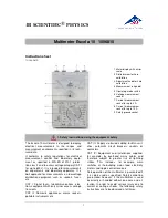
Escola 10
Brand: 3B SCIENTIFIC PHYSICS Pages: 6

1013526
Brand: 3B SCIENTIFIC PHYSICS Pages: 30

VC99 3 6/7 DMM
Brand: Vichy Pages: 5

UD77
Brand: Urrea Pages: 24

BR_SPY_mini
Brand: Technica Engineering GmbH Pages: 23


