background image

 Fax Number: 1-386-255-1589

 Information Email: [email protected]

 Phone Number: 1-386-255-1599

 Service Email: [email protected]

 Phone Number: 1-386-255-1599

www.JENNISONGAMES.com

For Additional Information or for an Electronic Copy of This Manual Visit Our Website

Jennison Entertainment Technologies Corporation

822 South Nova Road •


Daytona Beach, Florida 32114 •


U.S.A.

VERSION 0.5

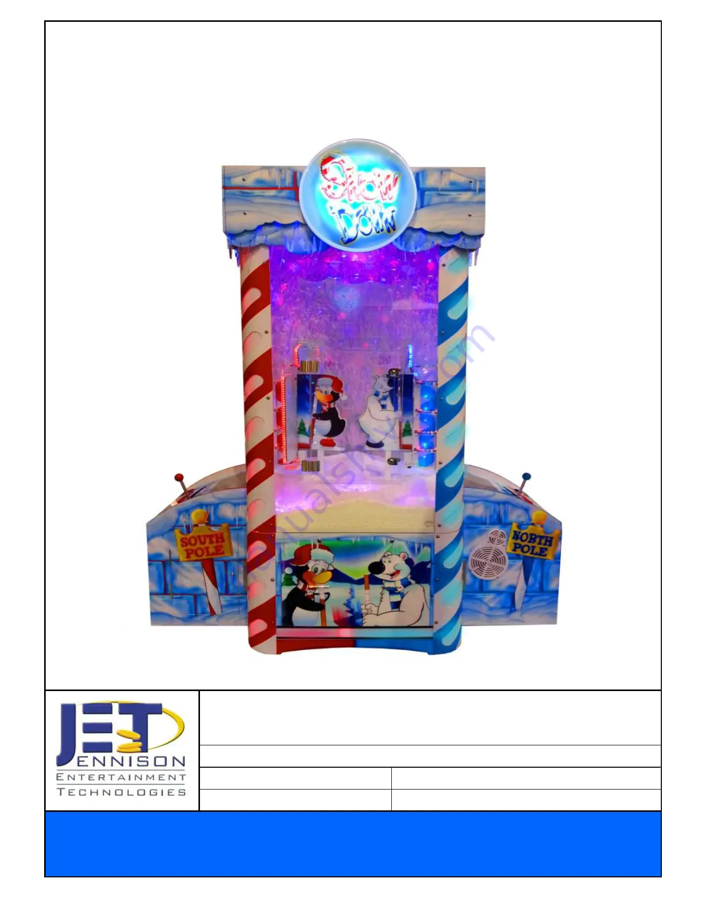
SNOW DOWN SERVICE MANUAL

Summary of Contents for SNOW DOWN

Page 1: ...ail Service JennisonGames com Phone Number 1 386 255 1599 www JENNISONGAMES com For Additional Information or for an Electronic Copy of This Manual Visit Our Website Jennison Entertainment Technologie...

Page 2: ...Table of Contents Section Adjusting the Payout Percentages Changing Cost Per Credit Changing Cost Per Ticket Setting Credits Required Setting Mercy Tickets Setting Game Score Values Setting Bonus Scor...

Page 3: ...LUE These messages are provided in cases where service personal must follow directions provided by J E T NOTICE Notices are given in GREEN boxes These messages are provided for the operator s convenie...

Page 4: ...ce twitching jerking or shaking of arms or legs disorientation confusion or momentary loss of awareness Seizures may also cause loss of consciousness or convulsions that can lead to injury from fallin...

Page 5: ...ide in this manual DANGER DO NOT remove the cabinet glass without first reading the removal instructions Do not attempt to remove the glass without at least two people DANGER SNOW DOWN SAFETY CAUTIONS...

Page 6: ...CAUTION Use appropriate care when servicing the game and ensure that all removed components are away from facility guests and children SNOW DOWN SAFETY CAUTIONS NOTICES Set the 115 230 VAC selector s...

Page 7: ...s A digital device pursuant to Part 15 of the FCC rules These limits are designed to provide reasonable protection against harmful interference when the equipment is operated in a commercial environme...

Page 8: ...on on Snow Down As of November 2013 Jennison Entertainment Technologies has tested all components used in the manufacturing of Snow Down All components have been found to be within the standards set f...

Page 9: ...ow Down ships on two 4 x 8 skids within the United States Canada and Mexico The main cabinet ships on one and the control centers header section ship on the other The skid that the main cabinet is on...

Page 10: ...O NOT OVERLOAD ANY CIRCUIT WITH THE ADDITION OF SNOW DOWN ENSURE THAT THE OUTLET HAS PROPER VOLTAGE BEFORE TURNING ON THE UNIT DANGER IF YOU CHOOSE TO CONVERT YOUR UNIT TO A DIFFERENT LINE VOLTAGE THA...

Page 11: ...TOR PRIOR TO CONTINUING NEITHER J E T OR YOUR DISTRIBUTOR IS RESPONSIBLE FOR ANY DAMAGE CAUSED DURING IMPROPER INSTALLATION PROCEDURES RED SECTIONS RED SECTION AREAS REQUIRE 2 OR MOR PEOPLE MINIMUM TO...

Page 12: ...s on one 4 X8 skid and the two component boxes are shipped on another 4 X8 skid Check Box When This Step is Complete Check Box When This Step is Complete PACKAGING AND PALLET MAY BE DIFFERENT THAN SEE...

Page 13: ...orklift or have a minimum for 3 people help to remove the header box off the top of the main cabinet This section weighs 170 pounds NOTICE PACKAGING AND PALLET MAY BE DIFFERENT THAN SEEN IN PHOTO Chec...

Page 14: ...Step 2 A INSTALLATION INSTRUCTIONS Removing the game from the pallet or skid Ensure that the forks are centered in the middle of the cabinet and do not pierce any part of the cardboard pallet Check Bo...

Page 15: ...When This Step is Complete INSTALLATION INSTRUCTIONS Step 2 C Removing the game from the pallet or skid Slowly lift the unit vertical and ensure that the pallet stays on the ground Move the pallet out...

Page 16: ...Step is Complete Step 3 B Removing the main cabinet packaging Remove all the protective packaging from the unit Please careful not to cut too deep Check Box When This Step is Complete Step 3 C Removin...

Page 17: ...art to remove this gently rotate the marquee so that it will come out Check Box When This Step is Complete INSTALLATION INSTRUCTIONS Step 4 Unboxing the marquee header Locate the marquee header box an...

Page 18: ...ach end to avoid cracking the plastic Snow Down marquee Check Box When This Step is Complete Step 4 E Removing the acrylic header marquee s Step 4 C Removing the acrylic header marquee s INSTALLATION...

Page 19: ...BINET HEADER ON THE GROUND UPSIDE DOWN THERE ARE BOARDS ON THE TOP THAT WILL GET DAMAGED Lifting the header cabinet out of the box Check Box When This Step is Complete Step 4 F Removing the header cab...

Page 20: ...header cabinet into place We recommend a minimum of three people to be present when lift the cabinet header into place Two people to lift the unit and the other person to attach the electrical connec...

Page 21: ...line Blue Brown Yellow Green going to the header power supply Step 4 L Lifting the header cabinet into place Locate the electrical connection in the corner of the header There are three connections th...

Page 22: ...er cabinet power cables Plug in the remaining three pin Molex connector This is the harness for additional low voltage LED lighting Check Box When This Step is Complete Step 4 P INSTALLATION INSTRUCTI...

Page 23: ...at side of the cabinet Red on Red It may be necessary to again lift the cabinet header to ensure it fits snuggly into position and is not angled in any fashion Check Box When This Step is Complete Che...

Page 24: ...ERIOD OF TIME Install the panel on the other side of the game and tighten all screws Note the color of the graphic on the header should match the color of that side of the cabinet Blue on Blue Locate...

Page 25: ...electrical When each piece was put into the box at the factory the piece was marked on the included piece of paper This ensures that all pieces required shipped with the game Do not discard the conten...

Page 26: ...TE that the color of the marquee should match the appropriate side of the cabinet Blue goes towards the Blue stripes and Red goes towards the Red stripes Check Box When This Step is Complete Check Box...

Page 27: ...quee to the header cabinet Some should hold the piece in place while the other person locates on installs the bolts NOTE that the color of the marquee should match the appropriate side of the cabinet...

Page 28: ...Step is Complete Step 6 K Connecting Electrical Connectors Connect the additional icicle LED lights to the available four pin Molex connectors There are a total of four separate connections for each s...

Page 29: ...ged into the header LED board It may be possible for this to vibrate out of the socket during shipping If it has not come out check to make sure it is secured Check Box When This Step is Complete Step...

Page 30: ...Check Box When This Step is Complete Step 7 C Pull wires out of the main cabinet Run this cord through an available hole in the bottom of the metal cabinet We suggest you use a hole closest to your po...

Page 31: ...This Step is Complete Step 7 F Unplug the power cord going to the computer Unplug the AC power cord going to the computer To prevent possible errors in monitor setup ensure that the computers AC power...

Page 32: ...computer is the remote control needed to operate the jacks to raise the cabinet into the proper position Check Box When This Step is Complete INSTALLATION INSTRUCTIONS Step 7 G Plug in the floor powe...

Page 33: ...gether The controls with the ORANGE cables are back ups Check Box When This Step is Complete Step 7 K Turn the game ON Locate the power switch and turn the power ON Check Box When This Step is Complet...

Page 34: ...thing catch immediately STOP raising the game and rectify the situation If the remote does not respond unplug or power OFF the game to stop power to the jacks WARNING CHECK TO MAKE SURE NO WIRES ARE C...

Page 35: ...ck 2 There is a number located next to each jack This number is engraved into the cabinet and corresponds to the number on the remote control In this case this is Jack 2 Step 7 P Raising the unit Ensu...

Page 36: ...keep the unit level CAUTION CONTINUE TO ENSURE ALL WIRES ARE FREE Check Box When This Step is Complete Step 7 S Locating jack 3 There is a number located next to each jack This number is engraved int...

Page 37: ...in the bolts and nuts They will be needed again to secure the permanent bracket Check Box When This Step is Complete Step 7 V Jack limit switches Each jack includes a limit switch so that when it reac...

Page 38: ...use the remote control to raise or lower different jacks to get the holes to align Pay attention to the numbers next to the jack and corresponding number on the remote WARNING DO NOT PUT YOU FINGERS...

Page 39: ...tep 7 Y 4 Lining up the holes Check Box When This Step is Complete Step 7 Y 5 Lining up the holes After the holes line up put the bolts through each hole Check Box When This Step is Complete Step 7 Y...

Page 40: ...rd are RED BROWN ORANGE BLACK If you plug in the wrong cable the lights may just be steady white and will not cascade Check Box When This Step is Complete Step 8 Plugging in the LED lights Check Box W...

Page 41: ...THE CABLE Check Box When This Step is Complete Step 8 C Check all nuts and bolts Check Box When This Step is Complete Step 8 B Plugging in the LED lights Plug the cable into the connector on the boar...

Page 42: ...10 Attaching the skirt panels Locate and install the four cabinet skirt pieces Be sure to match the color with the proper side of the game Check Box When This Step is Complete Step 10 A Securing the...

Page 43: ...roup of wires that are RED BLACK BLUE PURPLE Check Box When This Step is Complete Step 11 A Verifying the LED light connections are correct Ensure that he wire connection going to the skirt Horizontal...

Page 44: ...acket Check to make sure you use the appropriate bracket for each side S for South side and N for North side These have been tested in those positions and alignment is sufficient Check Box When This S...

Page 45: ...ter cabinets Check Box When This Step is Complete INSTALLATION INSTRUCTIONS Step 13 C Getting ready to power ON Secure the handle extension to the bearing bracket using the provided bolts and nuts Ins...

Page 46: ...This Step is Complete Step 14 C Installing the control centers The RED control center goes onto the side with the RED stripes Check Box When This Step is Complete Step 14 D Locating the power cables...

Page 47: ...nnections that must be made on the RED side WARNING DO NOT PLUG IN OR REMOVE THE MONITOR CABLE WITH THE COMPUTER TURNED ON Check Box When This Step is Complete Step 14 F Connection 1 Connect the 24 Pi...

Page 48: ...he wires There are two connections that must be made on the blue side Check Box When This Step is Complete INSTALLATION INSTRUCTIONS Step 14 H Connection 3 Connect the USB keypad Check Box When This S...

Page 49: ...BLE WITH THE COMPUTER TURNED ON INSTALLATION INSTRUCTIONS Step 15 B Connection 1 Check Box When This Step is Complete Step 15 C Getting ready to power ON Check Box When This Step is Complete Step 15 D...

Page 50: ...tal brackets to secure each control center to the main cabinet WARNING DO NOT OVERTIGHTEN Check Box When This Step is Complete Step 16 A Attaching the brackets Use the provided metric socket to tighte...

Page 51: ...the protective bristles and locate the handle bracket Check Box When This Step is Complete Step 18 A Insert the handle into each bracket Insert the handle into each handle bracket and rotate 180 degr...

Page 52: ...ep 18 E Installing the handle Install and tighten the first set of nuts Check Box When This Step is Complete INSTALLATION INSTRUCTIONS Step 18 C Installing the handle Use the provided nuts and bolts a...

Page 53: ...t of nuts Check Box When This Step is Complete Step 18 G Installing the handle Check to make sure the handle moves all the way to the left and all the way to the right and does not get caught in the m...

Page 54: ...dy to power ON Plug in the computer AC power cord we had disconnected earlier WARNING ENSURE THE GAME POWER IS TURNED OFF BEFORE INSERTING THE COMPUTER AC CORD Check Box When This Step is Complete Ste...

Page 55: ...ge is displayed on both monitors It may take up to two minutes for the PC to start 3 After the software starts check to make sure that LINK disappears and the INSERT COIN SWIPE CARD appears on screen...

Page 56: ...UNDERSTANDING THE SEG DISPLAY LOCATION BONUS SEG VALUES SEG DISPLAY 4 SEG DISPLAY 3 SEG DISPLAY 2 SEG DISPLAY 1 Jennison Entertainment Technologies Snow Down Service Manual Page 205...

Page 57: ...TANDING THE SCORE STATES SCORE VALUE SETS SCORE VALUES SET 1 SCORE VALUES SET 2 SCORE VALUES SET 3 SCORE VALUES SET 4 SCORE VALUES SET 5 Jennison Entertainment Technologies Snow Down Service Manual Pa...

Page 58: ...EG 3 18 20 18 20 18 SEG 2 12 14 16 12 14 SEG 1 6 10 12 6 10 BONUS 100 250 500 100 1000 SEG 4 30 40 50 30 40 BONUS 100 250 500 100 1000 SEG 4 30 40 50 30 40 This ticket payout table is for reference on...

Page 59: ...your payout percentage Step 1 Tools needed to change software file In order to modify the Notepad file in the Windows Snow Down folder you must have a wireless keyboard and mouse These are not include...

Page 60: ...ld be the CPU temperature information In Select Games NOTE In order to view the Windows Start icon you must be viewing the monitor on Player 1 RED side You must also orient the mouse to be on the task...

Page 61: ...tion files Under HARD DISK DRIVES click LOCAL DISCK D Step 8 Locating the Snow Down configuration files In the D DRIVE locate and open the SNOW_PLAYER_20130528 folder Please note that the name of this...

Page 62: ...named CONFIGURATION This is the file that we want to modify in order to change the default values within the Snow Down menu Because many features are linked to this file any input of corrupt informati...

Page 63: ...A4 lines Only modify the five values to the right of the equals sign To delete a value from one of the pre programmed settings place the mouse curser to the right of the value you wish to change Then...

Page 64: ...eStateC4 lines Only modify the five values to the right of the equals sign To delete a value from one of the pre programmed settings place the mouse curser to the right of the value you wish to change...

Page 65: ...file Click FILE and then click SAVE Step 19 Closing the Notepad file After saving the file you may then click on the X in the top right corner of the window and close the Notepad file Step 20 Closing...

Page 66: ...ame OFF remove the USB transmitter from the back of the computer Step 23 Turning the game ON After the transmitter has been removed and at least 45 seconds has elapsed from when the machine was shut d...

Page 67: ...SCORE STATE selection screens Verify that the values you entered above are now reflected under each score state A B C D Choose the desired score state and select SAVE After saving push and hold the b...

Page 68: ...LAYER 1 RED SINGLE PLAY BUTTON 20 21 16 17 U11 IS NOT UTLIZED IN SNOW DOWN THIS SPARE IC CAN BE USED IN U08 U09 TO RECITFY POTENTIAL ISSUES WITH THOSE IC S IF YOU SWAP IC S BE SURE TO PUT THE DEFECTIV...

Page 69: ...IC s should they become corrupt SNOW DOWN MAIN BOARD INPUT CHART CONTINUED IC INPUT CONTENT PICTURE U12 33 34 35 36 37 38 39 40 U12 IS NOT UTLIZED IN SNOW DOWN THIS SPARE IC CAN BE USED IN U08 U09 TO...

Page 70: ...R FAN 5 30 AMPLIFIER 31 BOTTOM CABINET LED LIGHTS RED 32 BOTTOM CABINET LED LIGHTS BLUE 33 PLAYER 1 COIN METER 38 PLAYER 1 SINGLE PLAY BUTTON LED 39 PLAYER 2 DOUBLE PLAY BUTTON LED 45 PLAYER 2 COIN AC...

Page 71: ...A SCORE NOT CURRENTLY USED BONUS NOT CURRENTLY USED WIN TWICE NOT CURRENTLY USED METER NOT CURRENTLY USED NOTICE SW31 SW32 SW33 SW34 SHOULD BE SET TO ON ALL OTHER DIP SWITCHES THAT ARE NOT USED SHOULD...

Reviews: