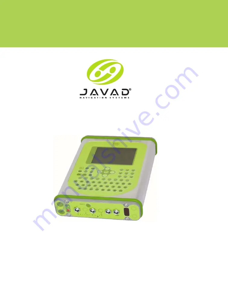
background image

Prego

Operator’s Manual

©Copyright Javad Navigation Systems, Inc. 

May, 2005

All contents in this manual are copyrighted by Javad Navigation Systems, Inc. All rights reserved. 

The information contained herein may not be used, accessed, copied, stored, displayed, 

sold, modified, published, or distributed, or otherwise reproduced 

without express written consent from JNS.


Summary of Contents for Prego

Page 1: ...contents in this manual are copyrighted by Javad Navigation Systems Inc All rights reserved The information contained herein may not be used accessed copied stored displayed sold modified published or distributed or otherwise reproduced without express written consent from JNS ...

Page 2: ......

Page 3: ...anadian Emissions Labeling Requirements XVI Manual Conventions XVII Chapter 1 Introduction Overview 1 2 Principles of Operation 1 2 GPS Overview 1 2 Calculating Positions 1 3 GPS Positioning 1 3 Conclusion 1 4 Receiver Overview 1 4 Standard Package Components 1 7 Cables 1 7 Software 1 7 Literature 1 8 Getting Acquainted 1 8 Internal Components 1 9 ...

Page 4: ...Powering the Prego 2 2 Internal batteries 2 2 External Batteries 2 2 Battery Charger 2 3 Turning On Off the Prego 2 3 Receiver 2 4 Windows CE Controller 2 4 Connecting the Prego and a Computer 2 4 Prego Configuration 2 6 Power Management 2 10 Charging Internal Batteries 2 14 Checking Internal Battery Status 2 15 Radio Configuration 2 15 MinPad Configuration 2 24 Calibrating the Windows CE Controll...

Page 5: ... 3 11 Real time Kinematic Measuring 3 12 Setting up an RTK Base Station 3 13 Setting up an RTK Rover 3 18 Chapter 4 Operation Using the MinPad 4 1 Status LED 4 2 FN Key and REC LED 4 2 Information Modes 4 5 Normal 4 6 Extended Information Mode EIM 4 6 Using the Integrated Controller 4 7 Touch Screen Functions 4 7 Keypad Functions 4 8 Downloading Files to a Computer 4 9 Deleting Files 4 12 Checking...

Page 6: ...e 4 22 Chapter 5 Troubleshooting Power Problems 5 1 Receiver Problems 5 2 Appendix A Creating Scripts Creating Scripts A 1 Appendix B Specifications Prego Specifications B 1 Connector Specifications B 8 Power Connector B 8 Serial RS232 Connector B 9 Serial RNGR Connector B 10 Radio Modem RF Connector B 10 GPS External Antenna RF Connector B 11 USB Connector B 11 ETHR Connector B 12 EVENT and 1PPS ...

Page 7: ... TA BL E OF CONTENTS Appendix C Safety Warnings Safety warnings C 1 General Warnings C 1 Internal Battery Pack Warnings C 2 Usage Warnings C 2 Appendix D Using the Radio Using the Radio D 1 Appendix E Warranty Terms Warranty Terms E 1 Index ...

Page 8: ...VI Prego Operator s Manual www javad com Notes ...

Page 9: ... Configuration PCView Main Screen 2 5 Click File Connect 2 5 Connection Parameters 2 6 PCView Connection Established 2 6 Configuration Receiver 2 7 Receiver Configuration 2 7 Receiver Configuration MinPad Tab 2 8 Receiver Configuration Advanced Tab 2 8 Advanced Configuration Multipath Reduction 2 9 Advanced Configuration Loop Management 2 9 File Disconnect then File Exit 2 10 Configuration Receive...

Page 10: ...ick Load 2 18 PDL Identification Tab 2 19 PDL Radio LInk Tab 2 20 PDL Serial Interface Tab 2 21 PDL Click Program 2 21 Click Close then Exit 2 22 Connection Parameters Manual Mode Only 2 22 Manual Mode Command Responses 2 23 MinPad 2 24 Connection Parameters MinPad Settings 2 25 Configuration Receiver 2 25 Receiver Configuration MinPad 2 26 Integrated Windows CE Controller 2 30 MS ActiveSync File ...

Page 11: ...o Rover Station Setup 3 18 Rover Tab Configuration 3 19 Rover Configuration Ports 3 20 PCView Main Screen 3 20 Chapter 4 Operation MinPad 4 1 Windows CE Controller Keypad 4 8 Connection Parameters RTS CTS Handshaking 4 10 File File Manager 4 10 Find Files to Download 4 11 Download Files 4 11 File Download in Progress 4 12 File Disconnect then File Exit 4 12 Connection Parameters RTS CTS Handshakin...

Page 12: ... 4 21 About PCView 4 21 FLoader Main Screen 4 23 Set Device Type 4 23 Program Tab Settings 4 24 Set Device Type 4 24 Program Tab Settings 4 25 Appendix B Specifications Power Connector B 8 RS232 Connector B 9 RNGR Connector B 10 USB Connector B 11 ETHR Connector B 12 ...

Page 13: ...hapter 2 Configuration Data Recording Parameter Behavior 2 29 Chapter 3 Setup and Measuring Antenna 2 Offset Measurements 3 3 Antenna 3 Offset Measurements 3 4 Chapter 4 Operation FN Key Functions and REC LED Status 4 4 Signal to Noise S N Good Ratios 4 6 Special Keys and Functions 4 8 Key Combinations 4 9 ...

Page 14: ...ications B 1 Power Connector Specifications B 8 RS232 Connector Specifications B 9 RNGR Connector Specifications B 10 Pacific Crest PDL UHF Modem Connector Specifications B 10 Spread Spectrum GSM Modem Connector Specifications B 11 External Antenna Connector Specifications B 11 USB Connector Specifications B 11 ETHR Connector Specifications B 12 ...

Page 15: ...nspecting or adjusting COPYRIGHT All information contained in this Manual is the intellectual property of and copyrighted material of JNS All rights are reserved You may not use access copy store display create derivative works of sell modify publish distribute or allow any third party access to any graphics content information or data in this Manual without JNS express written consent and may onl...

Page 16: ...N ANY EVENT JNS SHALL HAVE NO LIABILITY FOR DAMAGES OR OTHERWISE TO YOU OR ANY OTHER PERSON OR ENTITY IN EXCESS OF THE PURCHASE PRICE FOR THE PREGO LICENSE AGREEMENT Use of any computer programs or software supplied by JNS or downloaded from a JNS website the Software in connection with the Prego constitutes acceptance of these Terms and Conditions in this Manual and an agreement to abide by these...

Page 17: ...may seek a protective order or other appropriate remedy WEBSITE OTHER STATEMENTS No statement contained at the JNS website or any other website or in any other advertisements or JNS literature or made by an employee or independent contractor of JNS modifies these Terms and Conditions including the Software license warranty and limitation of liability SAFETY Improper use of the Prego can lead to in...

Page 18: ...antee that interference will not occur in a particular installation If this equipment does cause interference to radio or television equipment reception which can be determined by turning the equipment off and on the user is encouraged to try to correct the interference by on or more of the following measures Reorient or relocate the receiving antenna Move the equipment away from the receiver Plug...

Page 19: ...ation system performance measurements or personal safety CAUTION Notification that an action has the potential to adversely affect system operation system performance data integrity or personal health WARNING Notification that an action will result in system damage loss of data loss of warranty or personal injury DANGER UNDER NO CIRCUMSTANCES SHOULD THIS ACTION BE PERFORMED Example Description Fil...

Page 20: ...XVIII Prego Operator s Manual www javad com Notes ...

Page 21: ...tor s Manual 1 1 INTRODUCTION 1 This chapter describes The Prego Figure 1 1 Common Prego features and functions Standard package contents Getting acquainted with Prego components The Option Authorized File OAF Figure 1 1 Prego ...

Page 22: ...nt of Defense DoD is a network of up to 28 satellites orbiting the earth every 12 hours The Global Navigation Satellite System GLONASS is the Russian Federation Ministry of Defense counterpart to GPS At any one time with a standard 15 degree angle up to 10 or 12 GPS satellites are visible from any point on earth When a receiver can also track GLONASS satellites between 10 and 16 satellites are vis...

Page 23: ...e receiver must lock onto a fifth satellite Six satellites will provide fault tolerance in mixed scenarious Usually the number of GPS and GLONASS satellites in view does not exceed twenty 20 Once locked on to a satellite the receiver collects ephemerides and almanacs saving this information to its NVRAM Non Volatile RAM GPS and GLONASS satellites broadcast ephemeris data cyclically with a period o...

Page 24: ...mixed scenarios Current ephemerides and almanacs Several algorithms to detect and correct faulty information Conclusion You can use JNS GPS receivers to collect data from a network of satellites and control stations to triangulate precise points anywhere on Earth This overview simply outlines the basics of GPS and GLONASS positioning For more detailed information visit the JNS website www javad co...

Page 25: ...ed using a post processing software package When the receiver is run in RTK mode raw data measurements are recorded into the receiver s internal memory This allows the operator to double check real time results obtained in the field The Prego receiver has the following operation modes Stand alone positioning Relative differential positioning with two or more receivers running simultaneously and po...

Page 26: ...n PDL Base power consumption measured at 12 5 VDC The radio coverage of 2 Watt transmitter varies from 1 5 km up to 3 0 km If there is a clear line of sight between the base and rover the coverage is increased up to 5 6 km Notice Some countries require licensing to use the radio spectrum National radio regulatory organizations control this licensing process Spread spectrum modem 915 MHz JNS Spread...

Page 27: ...tectors 10 Cables Standard package cables include Receiver to computer RS 232 serial cable Receiver to SAE power cable SAE to SAE cable extension Receiver to receiver cross over cable RNGR output Power charger cable Power supply W 48 SAFECO connector Software Standard Prego software includes PCView Lite controller software that runs on a Windows based computer Please refer to the PCView User s Man...

Page 28: ...ting and caring for your Prego receiver These are available on the JNS website www javad com PCView User s Manual GPS Receiver Interface Language GRIL manual FLoader User s Manual MinPad User s Manual Getting Acquainted This unit has a total weight of 1 9 kg The receiver s advanced design allows users to significantly reduce the number of cables required for receiver operation allowing the user to...

Page 29: ...s Manual for detailed information on PCView Lite Integrated Controller The Prego has an integrated Windows CE ver 3 0 controller with 32 MB of SDRAM 32MB 64 MB optional of flash disk storage and a 133 MHz processor The 133 MHz Intel StrongARM CPU provides over 145 MIPS Millions of Instructions Per Second and the 100 MHz SDRAM memory provides twice the throughput of older DRAM technology The contro...

Page 30: ...o capture RTK corrections a PDL Base station broadcasts The PDL Base operator is responsible for complying with local regulations for radio operation In the US the FCC regulates the use of radio transmitters requiring a license Broadcasting without a license can result in severe penalties including the confiscation of your radio and GPS equipment Please call JNS Customer Support if you need advice...

Page 31: ...rd has a processor and firmware independent of the receiver card To ensure firmware compatibility both the GPS receiver board and power board must be loaded with firmware from the same package Batteries Your Prego receiver is equipped with two Lithium Ion battery packs connected to the receiver s power board Each one of these Lithium Ion battery packs is 7 4 V and 5 4 Ah giving you a total power o...

Page 32: ...er interface and to provide connections for external devices Figure 1 2 Figure 1 2 Prego Panels Top Panel Figure 1 3 shows the top panel components Figure 1 3 Prego Top Panel Modem The modem antenna connector used for RF connection of the internal modem This is a BNC female connector for Pacific Crest PDL UHF modems and a TNC female connector for spread spectrum and GSM modems ...

Page 33: ... time 1PPS The BNC connector for 1 pulse per second 1PPS generates 1PPS signals with programmable reference time period and offset synchronized to a specified reference time Front Panel Figure 1 4 shows the front panel components Figure 1 4 Prego Front Panel For more information on using the touch screen and keypad see Using the Integrated Controller on page 4 7 Windows CE controller touch screen ...

Page 34: ... Power Mode or if the receiver does not respond to commands See Using the MinPad on page 4 1 for more information on the Reset key A This serial port is used for communication between the Prego and the external controller computer external radio modem or other devices B This serial port is installed upon request and only when the internal controller is absent If the internal controller is present ...

Page 35: ...re available on the market JNS can guarantee performance specifications of the Prego only when used with JNS antennas Use the following antenna type MarAnt The internal LNA low noise amplifier of this antenna accepts voltages between 2 7 V to 12 V If you decide to use a third party antenna make sure that the antenna s LNA can handle the 5 V of power the Prego provides To connect the antenna to the...

Page 36: ...ailable options and details visit the JNS website www javad com or consult your JNS dealer Type of signal standard L1 optional L2 Memory standard 0Mb optional 1Mb up to 96Mb Update rate standard 1Hz optional 5 10 or 20Hz RTK at 1Hz 5Hz 10Hz and 20Hz RTCM CMR Input Output Event marker Common tracking Advanced multipath reduction Wide area augmentation system WAAS Receiver autonomous integrity monit...

Page 37: ...lmanacs Before you can use your Prego you need to 1 Charge the batteries See Powering the Prego on page 2 2 1 Configure and calibrate as needed the various parts of your receiver See Connecting the Prego and a Computer on page 2 4 Prego Configuration on page 2 6 Radio Configuration on page 2 15 MinPad Configuration on page 2 24 and Calibrating the Windows CE Controller on page 2 30 2 Collect an al...

Page 38: ... charge in Zero Power Mode see Zero Power Mode on page 4 20 for more information 4 Leave overnight An eight hour charge will charge the batteries about 90 A ten hour charge will fully charge the receiver The internal batteries cannot be overcharged The speed of the charge depends on Power and Charger settings on the PCView Receiver Configuration screen and whether the receiver and controller are t...

Page 39: ... that the charger mode is set to off Otherwise the external batteries will also charge internal batteries causing operation time to decrease See Power Management on page 2 10 for more information on setting the charger mode Battery Charger The same charger used to charge the Prego internal batteries can be used as an external power supply for the receiver The charger is provided with the receiver ...

Page 40: ...oller To turn On the controller press the green On key on the front panel of the Prego To turn Off the controller press the green On key on the front panel of the Prego Hold down the On key for approximately eight seconds to perform a hard reset of the controller Connecting the Prego and a Computer To configure manage files or maintain the Prego you need to connect the receiver and a computer usin...

Page 41: ...main screen displays Figure 2 1 Figure 2 1 PCView Main Screen 3 Click File Connect Figure 2 2 Figure 2 2 Click File Connect 4 On the Connection Parameters dialog box select the following parameters and click Connect Figure 2 3 on page 2 6 Set the Connection mode Direct Set the port for your computer typically COM1 from the Port drop down list ...

Page 42: ...ow of PCView A timer will begin to count up in the lower right corner as well Figure 2 4 Figure 2 4 PCView Connection Established Prego Configuration You use PCView to configure the various parts of the Prego receiver Any settings you make using PCView will be saved in the Prego receiver s memory and will be reflected when you use the MinPad You can change the receiver s configuration in the field...

Page 43: ... your receiver and computer See Connecting the Prego and a Computer on page 2 4 for this procedure 1 Once connected click on Configuration Receiver Figure 2 5 Figure 2 5 Configuration Receiver The Receiver Configuration dialog box displays Figure 2 6 Figure 2 6 Receiver Configuration 2 Click the MinPad tab configure the following settings and click Apply Figure 2 7 on page 2 8 Set the Recording in...

Page 44: ...etc and or the antenna location is near reflective objects configure the receiver to reduce errors from these sources in the Advanced tab Warning Do not make other changes without consulting the PCView User s Manual 1 Click the Advanced tab on the Receiver Configuration screen Figure 2 8 Figure 2 8 Receiver Configuration Advanced Tab 2 Click the Multipath Reduction tab enable the following boxes a...

Page 45: ...n Figure 2 9 Advanced Configuration Multipath Reduction 1 Click the Loop Management tab enable the following boxes and click Apply Figure 2 10 Enable Common tracking Static Mode Figure 2 10 Advanced Configuration Loop Management 2 Click OK to close the Receiver Configuration screen ...

Page 46: ...eceiver s power The complete description of PCView exceeds the scope of this manual but can be found in the PCView User s Manual The latest copy of this manual can be downloaded from the JNS website The Prego can be connected to a computer using an RS232 serial cable and the PCView software program To access the tab controlling the power settings of your receiver take the following steps 1 Connect...

Page 47: ...attery A Battery B receiver will consume power from battery B External receiver will use an external power supply Figure 2 13 Select Power Mode 4 Select the Charger Mode drop down list to set the desired charger mode Figure 2 14 Current Mode displays the charging battery Figure 2 14 Select Charger Mode Off receiver will not charge batteries Charge A receiver will charge only battery A Charge B rec...

Page 48: ...urned on If the receiver is turned off there will not be any power on the ports Off the power will be absent even if the receiver is turned on Always the power board will deliver voltage on pin 1 of all serial port connectors even if the receiver is turned off 6 Select the Power output modes Slots drop down list to set power output on internal slots Figure 2 16 Figure 2 16 Select Power Output Mode...

Page 49: ...ltages Information External displays the external power supply s voltage On Board displays the voltage drawn by the receiver board Battery A displays the voltage of battery A Battery B displays the voltage of battery B Charger displays the charger s output voltage during battery charging 8 Select and check each of the Turn on off Slots check boxes to enable the corresponding internal slots Figure ...

Page 50: ... page 2 10 for setting these parameters The receiver or the on board controller is turned on Power Mode is set to External and Charger Mode is set to Auto 1 Plug the power charger cable into the power input port 2 Plug the power charger cable into an available outlet 3 Press the Reset key on the receiver This will ensure that the receiver is in Normal mode for charging The receiver will not charge...

Page 51: ...he About PCView screen A fully charged battery should indicate 8 2 to 8 4 V Radio Configuration The internal PDL radio in your Prego and the base radio can be configured differently depending of your needs and working conditions Use PCView and the PDL configuration program from Pacific Crest included with the base station to Access the internal PDL modem Configure the modem Check or change the mod...

Page 52: ...each command Figure 2 20 on page 2 17 set dev ser c rate 38400 set dev ser c echo cur term set dev ser c imode echo set cur term eoff QUIT set cur term echo dev null set cur term imode echo set cur term echo dev ser c The Manual Mode screen will show RE002 in response to each of these commands When finished you should have seven responses Figure 2 20 on page 2 17 Tip Save this set of commands to a...

Page 53: ...mation on manual commands refer to the GPS Receiver Interface Language Manual 3 Click Disconnect Figure 2 20 4 Run the PDL Radio Configuration Program pdlconf exe from Pacific Crest Make sure you have the latest version 2 10 or higher This software is also available at www paccrst com Figure 2 21 Figure 2 21 PDL Radio Configuration Main Screen ...

Page 54: ...ific Crest logo in the upper left corner of the main screen Figure 2 22 Figure 2 22 PDL Top Left Corner Icon Menu 6 From the pop up menu click Set Capture Method Soft Break Figure 2 23 Figure 2 23 PDL Set Capture Method Soft Break 7 Click Load to connect to the radio Figure 2 24 Figure 2 24 Click Load ...

Page 55: ...iguration 8 On the Identification tab type Owner information Figure 2 25 Figure 2 25 PDL Identification Tab The Identification screen supplies current information concerning firmware revision serial number frequency and power It also allows for the input of Owner information ...

Page 56: ...the following parameters Figure 2 26 Manual enable Channel TX RX set channel and frequency as desired Link Rate leave at 9600 requires a modulation type of GMSK Digisquelch set on High for Rover Low for Base station Forward Error Correction disable Scrambling enable Local Address leave at 0 Figure 2 26 PDL Radio LInk Tab ...

Page 57: ...ollowing parameters Figure 2 27 Baud Rate 38400 Parity None Notice Parity should always be set to None Mode Transparent w EOT Timeout Figure 2 27 PDL Serial Interface Tab 11 If you made changes click the Program button on the left of the screen to save setting changes to the modem s memory Figure 2 28 Figure 2 28 PDL Click Program ...

Page 58: ...Link characteristics except Digisquelch and Serial Interface parameters 13 Open PCView 14 Click File Connect 15 On the Connection Parameters screen select a baud rate of 38400 and enable the Manual mode only check box Figure 2 30 then click Connect Figure 2 30 Connection Parameters Manual Mode Only 16 On the Manual Mode screen write the following commands pressing Enter or clicking Send command af...

Page 59: ...adio Configuration QUIT set cur term imode cmd set dev ser c echo dev null set dev ser c imode cmd set dev ser c rate 38400 set cur term rate 115200 Figure 2 31 Manual Mode Command Responses 1 Click Disconnect Continue with other configuration or operation functions ...

Page 60: ...e MinPad allows the user to perform various functions Turn the receiver On or Off put it in Sleep mode or Zero power mode Turn data recording On or Off FN key Show the number of GPS green and GLONASS orange satellites being tracked STAT LED Show data recording status REC LED Show each time data is recorded to internal memory REC LED Show the status of post processing mode static or dynamic during ...

Page 61: ...ing parameters and click Apply Figure 2 35 on page 2 26 See the following pages for descriptions of these parameters Recording interval on page 2 26 Elevation mask for Log file on page 2 26 File name prefix on page 2 26 Always append to the file on page 2 27 Files Creation mode on page 2 27 Automatic File Rotation Mode AFRM on page 2 27 FN key mode on page 2 28 Initial data collection dynamic mode...

Page 62: ...le parameter This parameter specifies the minimum elevation angle for the satellites whose data will be put in the receiver files logged via MinPad when pressing FN The default value is five degrees File Name Prefix parameter This parameter specifies what prefix will be added to the names of the receiver files created via MinPad when pressing FN The prefix can be up to 20 characters long The defau...

Page 63: ... to Phase More precisely a new log file opens immediately before the scheduled epoch causing data tagged with this epoch to be recorded into the new log file When opening a new log file the receiver enables the default set of messages outputted with the default output period Both the default set of messages and the default output period are programmable Period specifies the time duration of each l...

Page 64: ...ed less than 1 second release to change the information mode Normal or Extended Information EI Modes FN pressed from 1 to 5 seconds release to start stop recording Static post processing mode Occupation mode switch pressing FN less than one second will insert into the corresponding log file a message indicating that the measuring type has been changed from static to kinematic or vice versa If the ...

Page 65: ...er is restored Receiver will resume data logging to the same file when power is restored Receiver will resume data logging to the same file when power is restored 2 Receiver data logged to default file Data logging will not resume when power is restored A new log file will open when power is restored and data will log to this file A new log file will open when power is restored and data will log t...

Page 66: ...n the controller and your computer See Establishing a Partnership on page 2 31 Touch Screen Calibration The screen on the integrated Windows CE controller is sensitive to the touch of a finger or stylus This touch screen functions similar to that of a traditional mouse Simple use a stylus or your finger to touch the commands you want To begin using the touch screen function you must first calibrat...

Page 67: ...your Prego receiver s integrated controller i e copying your personal files or measuring jobs installing programs on the controller from the PC and so on If Microsoft ActiveSync is already installed on your PC you can skip this installation 1 Download MS ActiveSync This software is free and is available on the Microsoft website www microsoft com downloads 2 After the file msasync exe downloads ont...

Page 68: ...omputer and run MS ActiveSync 6 Click on File Get Connected Figure 2 37 Figure 2 37 MS ActiveSync File Get Connected 7 Tap Yes on your controller when Connect to desktop appears to start the connection Figure 2 38 Connect to Desktop The software will search for any device connected to the communication port Figure 2 39 Connecting Controller and Computer If the connection has trouble click File Con...

Page 69: ...ve to try again if the first attempt was unsuccessful 11 To disconnect the controller and PC click File Connection Settings and disable the Allow serial cable or infrared connection to this COM port Notice If you do not disconnect ActiveSync will continue to use this port and it will be unavailable for other devices Collecting Almanacs Each satellite broadcasts a message almanac which gives the ap...

Page 70: ...receiver Notice If 15 minutes have passed and the receiver does not lock onto satellites to acquire an almanac you may need to clear the NVRAM See Clearing the NVRAM on page 4 18 for this procedure You will need to collect or update the almanac If the receiver has been off for a long time If the last known receiver position stored in the NVRAM is different from the present position by several hund...

Page 71: ...up the antenna and measure its height See Setup Antenna on page 3 1 and Measure the Antenna Height on page 3 2 1 Set up the Base and Rover receivers See Setup Receiver on page 3 5 2 Begin collecting data See Collect Data on page 3 5 Setup Antenna This section assumes you have already configured your receiver using PCView 1 Center the antenna over the point at which data will be collected For most ...

Page 72: ...ollowing Measured height of the antenna above the station marker Method of measuring the antenna height Model of the antenna used Antennas have two types of measurements Vertical measured from the marker to the antenna reference point ARP located on the bottom of the antenna at the base of the mounting threads Slant measured from the marker to the lower edge of the antenna slant height measure mar...

Page 73: ...anual 3 3 SE TUP AND MEASUR ING Prego Setup Figure 3 1 Antenna Offset Measurements Table 3 1 Antenna 2 Offset Measurements Antenna Radius A Vertical Offset L1 C Slant Offset L1 Antenna 2 0 122m 0 399 ft 0 054m 0 176 ft 0 021m 0 069 ft ...

Page 74: ...easures is called the Phase Center of the antenna This is analogous to the point at which a distance meter measures in a prism A user must enter the prism offset to compensate for this point not being at a physical surface of the prism Table 3 2 Antenna 3 Offset Measurements Antenna Radius A Vertical Offset L1 C Slant Offset L1 Antenna 3 0 123m 0 4 ft 0 114m 0 37 ft 0 033m 0 11 ft ...

Page 75: ...k red at first 6 Once the receiver has locked onto satellites the STAT light will blink green for GPS satellites orange for GLONASS satellites and a short red blink indicating it has not solved a position 7 Once the short red blink is gone the receiver has a position and measuring can be started You should wait until there is no red blink before starting data collection This ensures that the recei...

Page 76: ...baseline during a certain period of time These two receivers track four or more common satellites have the same data logging rate 5 30 seconds and the same elevation mask angles The length of the observation sessions can vary from a few minutes to several hours The optimal observation session length depends on the user s experience as well as the following factors The length of the baseline measur...

Page 77: ...the steps the operator should take to perform a static measuring using MinPad 1 Connect your receiver and computer See Connecting the Prego and a Computer on page 2 4 for this procedure 2 Using PCView click Configuration Receiver MinPad and specify the following parameters or specify parameters according to your particular job then click Apply Figure 3 3 on page 3 7 Recording Interval 15 seconds E...

Page 78: ...anagement tab and set the following parameters then click Apply Figure 3 5 Enable Common tracking enable Static mode enablel Figure 3 5 Advanced Loop Management 5 Set up the receiver or an external antenna and receiver as described in Prego Setup on page 3 1 Kinematic Measuring You can use the kinematic measuring method in two ways Stop and Go measuring Kinematic continuous measuring ...

Page 79: ...ime for points depends on the same factors as for the static measuring method Remember that both the Base station and Rover must collect data from the same satellites at the same data recording rate and with identical elevation mask angles This method of GPS measuring allows operators to reduce point occupation time permitting field crews to measuring more points as compared to other measuring met...

Page 80: ...ill be orange 5 Check the STAT light for satellites tracked 6 When finished quickly press and release the FN key to assign the Rover to kinematic Notice Remember if the REC LED blinks green the current mode is dynamic if it blinks orange the current mode is static 7 Move the Rover to the next location measuring point and press the FN key for less than a second to collect the data in static mode fo...

Page 81: ...itialized on the fly After the measuring completes data the receivers collect can be downloaded onto a computer and processed using post processing software for example Ensemble 1 Using PCView configure and set up the Base station as described in Static Measuring on page 3 6 2 Using PCView click Configuration Receiver MinPad and configure the Rover with the following parameters then click Apply Fi...

Page 82: ...eld notes 6 Press the FN key for one to five seconds to begin logging data in kinematic mode the antenna status is kinematic 7 Move the Rover receiver along the selected trajectory 8 Once the Rover receiver reaches the end point of the trajectory pause for several minutes 9 When finished press the FN key to stop logging data and turn off the Rover 10 Stop data logging and turn off the Base station...

Page 83: ...tation receiver s antenna as described in Setup Antenna on page 3 1 2 Connect an external modem to port C The internal radio should already have been configured 3 Set up hardware as shown in Figure 3 8 This setup shows a Base station setup Figure 3 8 Base Station Setup Notice Connect the radio antenna before switching the modem to the transmitting mode measuring Plumb Base station antenna over mea...

Page 84: ...ng the Prego and a Computer on page 2 4 for this procedure 7 Click Configuration Receiver 8 Restore the receiver s default settings Click the Set all parameters to defaults button located at the bottom of the Receiver Configuration screen Figure 3 9 Figure 3 9 Set All Parameters to Defaults 9 On the Receiver Configuration screen select the MinPad tab and specify your desired settings See the PCVie...

Page 85: ... set the following parameters Figure 3 11 on page 3 16 GPS GLO at one time enable Antenna position enter Lat Lon and Alt values OR Click Get from receiver OR Select Averaged and enter the Averaged Span in seconds then click Apply Click Tools Reset receiver and wait until the specified interval span completes Examine the Base coordinates on the Base tab they should correspond to the coordinates obt...

Page 86: ... set the following port parameters Figure 3 12 on page 3 17 Output drop down list select type and format of differential corrections Period sec enter interval at which receiver will generate differential corrections Baud rate drop down list select a baud rate i e the rate with which differential messages will be transmitted from receiver to modem Notice For Pacific Crest PDL UHF modems use a 38400...

Page 87: ...e previous steps press the power button on the external modem 15 Select the radio transmission power using the Low High toggle on the rear panel of the modem When in High the AMP PWR LED will be turned on 16 Use the Channel button to set the frequency channel Check that the modem transmits the corrections the TX LED will blink red each time the data is transmitted For more details on the settings ...

Page 88: ...ws the hardware setup for a Rover station with the Prego on a bipod Figure 3 13 Prego Rover Station Setup 1 Set up the Rover station receiver s antenna as described in Setup Antenna on page 3 1 2 Connect the receiver and your computer as described in Connecting the Prego and a Computer on page 2 4 3 Click Configuration Receiver 4 Select the Positioning tab and set the Position Masks Elevation mask...

Page 89: ...will compute either a delayed RTK position for the epoch to which the newly received RTCM CMR message corresponds or the current stand alone position while waiting for new RTCM CMR messages coming from the base Select the Dynamics of the antenna status during RTK either Static or Kinematic Specify the Ambiguity fixing level The Ambiguity Fixing Level radio buttons govern the process of the RTK eng...

Page 90: ...o receiver Notice For Pacific Crest PDL UHF modems use a 38400 baud rate For Spread Spectrum 915 MHz 2 4 GHz modems use a 19200 baud rate Figure 3 15 Rover Configuration Ports 7 Click Apply 8 Click OK to close the Receiver Configuration screen 9 On the main screen Figure 3 16 check the LQ field to ensure the receiver obtains differential corrections Usually the receiver will start to output the co...

Page 91: ...information Data link quality in percentage Time in seconds elapsed since the last received message Total number of received correct messages Total number of received corrupt messages If the receiver is not for some reason receiving differential corrections or if none of the ports have been configured to receive differential corrections the LQ field will either be empty or it will look like this 1...

Page 92: ...3 22 Prego Operator s Manual www javad com Notes ...

Page 93: ...sing the MinPad Using the touch screen and keypad Downloading Prego files to a computer Deleting receiver files Checking options and loading an OAF Managing Prego memory Clearing the NVRAM Changing receiver modes Checking and loading firmware Using the MinPad The MinPad Figure 4 1 is JNS s simple user interface used to display and control data input and output Figure 4 1 MinPad ...

Page 94: ...are problem or contains an improper OAF see Option Authorized File OAF on page 1 15 for more information on OAFs The REC LED blinks green or orange each time data is written to the internal receiver s memory You set the data recording time interval using PCView See Recording Interval parameter on page 2 26 for information on setting this function Each time you turn off or on data recording either ...

Page 95: ...le for CDU control display unit applications or for data recording This operation may require from fractions of a second to several minutes depending on the circumstances and the amount of internal memory Table 4 1 on page 4 4 summarizes FN key functions and REC LED statuses See FN Key Mode parameter on page 2 28 for information on setting FN key modes ...

Page 96: ...econd If FN key mode is LED blink mode switch Orange Release to change information mode If FN key mode is Occupation mode switch Orange No function Press 1 5 seconds If FN key mode is LED blink mode switch Green Release to start data recording post processing occupation mode undefined If FN key mode is Occupation mode switch Green Release to start recording Kinematic or Static post processing occu...

Page 97: ...h Green Data recording started Kinematic post processing occupation mode Orange Data recording started Static post processing occupation mode Press 1 second If FN key mode is LED blink mode switch Orange Release to change information mode If FN key mode is Occupation mode switch Orange Release to toggle between Static and Kinematic post processing modes Press 1 5 seconds No light Release to stop d...

Page 98: ... blink that shows the overall status of tests performed in EIM Its color is calculated from colors of other blinks It is orange if at least one of blinks is orange It is red if no other blinks are orange and there is at least one red blink It is green in all other cases Enough data for position computation GPS S N signal to noise ratio is good see Table 4 2 GLONASS S N ratio is good see Table 4 2 ...

Page 99: ...uld be green within 15 minutes of powering on Green ok Orange wait Red some tests failed 3 To switch back to normal press and quickly release the FN key Using the Integrated Controller The Prego includes an integrated controller that allows you to change settings enter data and make selections in the field Touch Screen Functions The integrated Windows CE controller uses a touch sensitive screen to...

Page 100: ...ic letters and numbers and punctuation comma period exclamation mark and so on keys These keys allow data entry Special keys function keys arrow keys and so on These keys can change the function of other keys move the cursor or insertion point right left up or down etc Table 4 3 lists particular keys and their function Table 4 3 Special Keys and Functions Key Function on Turns the receiver on off ...

Page 101: ...Activate the selected item arrow Moves cursor or insertion point Table 4 4 Key Combinations Key Combination Function shf on Turns the backlight on off ctrl C Copy ctrl V Paste shf Del Delete file in Explorer alt or alt Display contrast shf ctrl on Soft reset on held for 5 8 seconds Hard reset alt tap on item Displays shortcut commands sam as right click on mouse alt ctrl Touch screen calibration c...

Page 102: ...ur computer and delete files from the Prego When your survey finishes you can download your survey files to a computer for storage post processing or backup 1 Connect your receiver and computer See Connecting the Prego and a Computer on page 2 4 for this procedure AND Enable RTS CTS handshaking Figure 4 3 Figure 4 3 Connection Parameters RTS CTS Handshaking 1 Click File File Manager Figure 4 4 Fig...

Page 103: ...ownload and store files OR Type a new folder name and click Create to create a new folder in which to download and store files Open this new folder 4 Select the Download files tab 5 Select the file s you want to download Figure 4 6 on page 4 11 To select multiple files hold down the Shift key and click on nonsequential files to select several files at once or hold down the Ctrl key and click in in...

Page 104: ...ure 4 7 on page 4 12 Blue indicator file in queue for downloading Red indicator file currently downloading Green indicator file has successfully downloaded Figure 4 7 File Download in Progress 1 Click Exit on the File Manager screen 2 Click File Disconnect then File Exit to quit PCView Figure 4 8 Figure 4 8 File Disconnect then File Exit Deleting Files Use the following steps to delete files from ...

Page 105: ...ego and a Computer on page 2 4 for this procedure AND Enable RTS CTS handshaking Figure 4 9 Figure 4 9 Connection Parameters RTS CTS Handshaking 1 Click File File Manager Figure 4 10 Figure 4 10 File File Manager 2 On the Download files tab or Current log files tab select the file s you want to delete Figure 4 11 on page 4 14 ...

Page 106: ... files to select several files at once or hold down the Ctrl key and click in individual files Figure 4 11 Delete Files 3 Click Delete 4 Click Yes at the delete files confirmation dialog box The selected files will be deleted 5 Click Exit 6 Click File Disconnect then File Exit to quit PCView Figure 4 12 Figure 4 12 File Disconnect then File Exit ...

Page 107: ...s Manual for a more complete description of the PCView software 1 Connect your receiver and computer See Connecting the Prego and a Computer on page 2 4 for this procedure 1 Click on Tools Receiver Options Figure 4 13 Figure 4 13 Tools Receiver Options The Options Manager screen displays Figure 4 14 on page 4 16 and contains the following information Option name a name description of the option Cu...

Page 108: ...nd leased the Current status of the option displays the currently effective value 1 the firmware version does not support this option 0 the receiver option is disabled positive integer the option is enabled 1 When finished click Exit on the Option Manager screen then click File Disconnect to prevent conflicts with serial port management ...

Page 109: ...ue to each receiver Figure 4 15 Figure 4 15 Load OAF 3 Select the appropriate file and click Open Figure 4 15 The new OAF will load onto the receiver and the Option Manager table will update 4 When finished click Exit on the Option Manager screen then click File Disconnect to prevent conflicts with serial port management Managing Prego Memory When using your Prego in static or dynamic applications...

Page 110: ...e NVRAM in your Prego can be interpreted as a soft boot in your computer Tip Firmware versions 2 2p1 or higher keep the PDL modem on after clearing NVRAM After clearing the NVRAM your receiver will require some time to collect the new ephemerides and complete almanacs around 15 minutes Clearing the NVRAM of your receiver will not delete any of the files already recorded in your Prego s memory Howe...

Page 111: ...ur receiver and computer See Connecting the Prego and a Computer on page 2 4 for this procedure 2 Click Tools Clear NVRAM Figure 4 16 The REC LED rapidly flashes green and red the STAT LED flashes just red Figure 4 16 Tools Clear NVRAM 3 The receiver will automatically disconnect once the NVRAM is cleared Changing Receiver Modes The Prego receiver has four modes two information modes and two power...

Page 112: ...batteries This means that if you fully charge your receiver turn it off and store it the receiver will drain its battery power in less than 2 months To stop the power board from draining the batteries put your receiver in Zero Power Mode 1 Turn on your receiver 2 Press and hold the power key for more than eight seconds but less than 14 seconds the STAT and REC LEDs will turn orange then red 3 When...

Page 113: ...age 2 4 for this procedure 1 Click on Help About Figure 4 17 Figure 4 17 Help About The About PCView dialog box opens Figure 4 18 Figure 4 18 About PCView About PCView lists important information about the different hardware accessories and software properties This list includes the following which you will need if you contact JNS or your dealer Receiver model Receiver ID Firmware version 2 When f...

Page 114: ...ompress This file contains the following three files ramimage ldr the Receiver board RAM file main ldp the Receiver board Flash file powbrd ldr the Power board RAM file Notice You must load all three files when loading new firmware These files must come from the same firmware package The Prego uses FLoader a Windows based utility to load firmware onto the receiver board You can download FLoader to...

Page 115: ... 4 19 FLoader Main Screen 4 On the Connection tab select the COM port on the computer that connects with your receiver and select its speed usually 115200 Figure 4 19 5 Click the Device tab and set the Device Type as Receiver Figure 4 20 Figure 4 20 Set Device Type 6 Click Get from Device for Device Information ...

Page 116: ...for and select the Receiver board s RAM file ramimage ldr and Flash file main ldp Figure 4 21 9 Click Load and wait until 100 of the files load into your receiver Notice If you selected an incorrect RAM or Flash file an error message will display at the bottom of the dialog box Select the correct file 10 Click the Device tab and set the Device Type as Receiver s Power Board Figure 4 22 Figure 4 22...

Page 117: ...b Settings 12 Click Load and wait until 100 of the power board file load into your receiver Notice If you selected an incorrect RAM file an error message will display at the bottom of the dialog box Select the correct file 13 Click File Exit 14 Clear the receiver s NVRAM see Clearing the NVRAM on page 4 18 and update the almanac see Collecting Almanacs on page 2 33 after loading new firmware ...

Page 118: ...4 26 Prego Operator s Manual www javad com Notes ...

Page 119: ... PCView press Set all parameters to defaults Clear the NVRAM Initialize the file system this will erase all files inside the receiver Warning Do not attempt to repair equipment yourself Doing so will void your warranty and may damage the hardware Power Problems All Prego receivers are preset in the factory as Auto Mode for both the power and charger If you want to check these settings connect your...

Page 120: ...es are discharged Charge the batteries overnight See Powering the Prego on page 2 2 The receiver may have a defective charger or defective internal batteries If after charging your internal batteries overnight and your receiver is not powering contact JNS Customer Support for advice Problem The receiver cannot establish a connection to a computer or external controller Causes Solutions The cable i...

Page 121: ...a long period of time Causes Solutions The receiver stores an old almanac Update the almanac See Collecting Almanacs on page 2 33 Problem The receiver tracks too few satellites Causes Solutions The elevation mask value is too high e g above 15 degrees Lower the elevation mask See page 2 9 for information on setting the elevation mask The measuring is conducted near obstructions tree canopy tall bu...

Page 122: ...ng receiver options may be disabled or expired See Checking Options on page 4 15 for details on how to check current options Enable or prolong the validity of the corresponding receiver options by ordering a new OAF with the desired options activated There are not enough common satellites In order to obtain a fixed solution the Base and Rover should track at least five common satellites Ensure tha...

Page 123: ... format 1 Connect your receiver and a computer and start PCView See Connecting the Prego and a Computer on page 2 4 2 Click Configuration Receiver Ports and set the same input output format for both receivers The specified link rate is not compatible with the link rates the modem supports The link rate is the rate at which data transmits over the RF link Change the link rate to that which your mod...

Page 124: ...tween Base and Rover is too far Close the distance between the Base and Rover Use repeaters to increase radio coverage Problem The receiver does not start data logging Causes Solutions The receiver has no free space for files Download receiver files to a computer if needed and delete files see Downloading Files to a Computer on page 4 9 and Deleting Files on page 4 12 Use the AFRM feature See Auto...

Page 125: ...g each individual command Notice For more information on script files see the PCView User s Manual 1 Connect your receiver and computer 1 Start PCView 2 Click on File Manual Mode 3 Click Edit Script 4 Navigate to the folder in which you want to save the script file 5 Type a file name All files have a jpc extension For example Daisy_38400 jpc to enable the daisy chain and Daisy_Off jpc to disable t...

Page 126: ...al Mode dialog box 1 Navigate to the folder that contains your script file 2 Select the appropriate script file and click Load Table A 1 Script Commands To Create Daisy Chain To End Daisy Chain set dev ser c rate 38400 set dev ser c echo cur term set dev ser c imode echo set cur term eoff QUIT set cur term echo dev null set cur term imode echo set cur term echo dev ser c QUIT set cur term imode cm...

Page 127: ... cable connectors Prego Specifications This section lists Prego component details Table B 1 Prego Specifications Component Details Receiver Type Euro GGD set by activating the proper OAF G GPS L1 GD GPS L1 L2 GG GPS GLONASS L1 GGD GPS GLONASS L1 L2 Tracking Specifications Standard Channels 40 L1 GPS 20 L1 L2 GLONASS on Cinderella days see page B 7 for more information Optional Channels 20 GPS L1 L...

Page 128: ...L1 H 15mm 1 5ppm x D V 30mm 1 5ppm x D RTK For L1 L2 H 10mm 1 5ppm x D V 20mm 1 5ppm x D For L1 H 15mm 1 5ppm x D V 30mm 1 5ppm x D Cold Start Warm Start Reacquisition 60 sec 10 sec 1 sec Technology Common Tracking Multipath Reduction WAAS Adjustable PLL and DLL parameters Radio Modem Spread Spectrum Internal 900 MHz or 2 4 GHz Spread Spectrum transceiver UHF Radio modem Internal Rx or External Tx...

Page 129: ...T optional 1 PWR GPS Antenna GPS GLONASS Antenna External Antenna Type Microstrip zero centered Ground Plane Antenna on a flat ground plane or Choke Ring Memory Internal Memory Compact Flash Card Capacity Standard 0 MB Max 96 MB Logging Time 53 hours 8 MB 15 seconds L1 L2 and 7 satellites Logging Interval 0 05 to 86400 sec depending on the purchased options Power Internal battery Li ion 5400 mAh 7...

Page 130: ... Environment Operating temperature 10 C to 50 C with batteries Storage temperature 20 C to 35 C with batteries Physical Enclosure Aluminum extrusion rainproof Color JNS Green Dimensions W 159 x H 242 x D 49 mm Weight 1 9 kg NMEA NMEA version Ver 2 1 2 2 2 3 3 0 Messages GGA GLL GNS GRS GSA GST GSV HDT RMC VTG ZDA ROT Output interval 1 5 10 20 Hz 5 to 20 Hz is optional DGPS Correction format RTCM S...

Page 131: ... morning and evening Up to 32 km at noon Initialize time 5 seconds to 10 min depending on the base line length and multipath conditions Output interval for CMR RTCM 1 5 10 20 Hz 5 to 20 Hz is optional Elevation 0 to 90 deg independent with data logging Process interval 1 5 10 20 Hz 5 to 20 Hz is optional Latency Delay mode 20 msec 20 sec depends on latency which receives corrections data from base...

Page 132: ...ional Number of Event Marker port 1 Edge Rise Fall Reference time GPS GLONASS UTC USNO UTC SU Tracking Functions Multi path reduction optional Code Carrier PLL DLL setting Bandwidth order adjustable Common tracking loop setting On Off Static Mode Bandwidth of individual PLL Bandwidth of common PLL Smoothing interval Code Carrier WAAS EGNOS support Available Battery Charger AC Adapter Size W 60 x L...

Page 133: ...S or 7 GPS GLONASS satellites above 15 degrees in elevation and adherence to procedures recommended in this manual Notice In areas of high multipath during periods of high PDOP and during periods of high ionospheric activity performance may degrade Notice Robust checking procedures are recommended in areas of extreme multipath or under dense foliage Input AC 90 264 V 1A 110 V AC 47 63 Hz Output DC...

Page 134: ...ure B 1 is a sealed receptacle 5 pin connector with ODU part number G80F1C T05QF00 0000 Figure B 1 Power Connector Table B 2 gives power connector specifications Table B 2 Power Connector Specifications Number Signal Name Dir Details 1 Power_INP P 6 to 28 volts DC input 2 Power_INP P 6 to 28 volts DC input 3 Power_GND P Ground power return 4 Power_GND P Ground power return 5 Not used ...

Page 135: ...tacle 7 pin connector with ODU part number G80F1C T07QC00 0000 Figure B 2 RS232 Connector Table B 3gives the RS232 connector specifications Table B 3 RS232 Connector Specifications Number Signal Name Dir Details 1 Power_OUT P Power Output I 0 2 A 2 GND Signal ground 3 CTS I Clear to send 4 RTS O Request to send 5 RXD I Receive data 6 TXD O Transmit data 7 Not used ...

Page 136: ...m RF Connector The Pacific Crest PDL UHF modem connector type is a BNC Bulkhead Jack RF connector with an Applied Engineering Product part number of 6501 7051 003 Table B 4 RNGR Connector Specifications Number Signal Name Dir Details 1 Not Used 2 GND Signal ground 3 CTS I Clear to send 4 RTS O Request to send 5 RXD I Receive data 6 TXD O Transmit data 7 Not used Table B 5 Pacific Crest PDL UHF Mod...

Page 137: ...SB connector Figure B 4 is a sealed receptacle 5 pin connector with ODU part number G80F1C T05QF00 0000 Figure B 4 USB Connector Table B 8 gives the USB connector specifications Table B 6 Spread Spectrum GSM Modem Connector Specifications Type Signal Name Dir Details TNC Modem I O I O RF input from modem antenna Table B 7 External Antenna Connector Specifications Type Signal Name Dir Details TNC A...

Page 138: ... 9 gives the ETHR connector specifications 2 USB_PWR P Bus power 3 GND Ground 4 USB D I O Data plus 5 USB D I O Data minus Table B 9 ETHR Connector Specifications Number Signal Name Dir Details 1 Not used 2 GND Ground Link LED cathode 3 TXD O Transmit data plus 4 TXD O Transmit data minus 5 RXD I Receive data plus 6 RXD I Receive data minus 7 LINKLED O Link LED anode Table B 8 USB Connector Specif...

Page 139: ...rator s Manual B 13 APPENDIX Connector Specifications EVENT and 1PPS Connectors The EVENT and 1PPS connectors are coaxial female receptacles of BNC series Kings Electronics part number KC 79 108 These connectors are optional ...

Page 140: ...B 14 Prego Operator s Manual www javad com Notes ...

Page 141: ...ND RECORDING SUCH MEASUREMENTS THIS PRODUCT SHOULD NEVER BE USED WITHOUT THE USER THOROUGHLY UNDERSTANDING THIS MANUAL AFTER DISABLING SAFETY SYSTEMS OR ALTERING THE PRODUCT WITH UNAUTHORIZED ACCESSORIES WITHOUT PROPER SAFEGUARDS AT THE MEASURING SITE CONTRARY TO APPLICABLE LAWS RULES AND REGULATIONS THE PREGO SHOULD NEVER BE USED IN DANGEROUS ENVIRONMENTS USE IN RAIN OR SNOW FOR A LIMITED PERIOD ...

Page 142: ...tory authorized technicians will void the receiver s warranty Do not attempt to open the battery pack or replace it Do not disassemble the battery pack Do not charge in conditions different than specified Do not use other than the specified battery charger Do not short circuit Do not crush or modify Usage Warnings CAUTION If this product has been dropped altered transported or shipped without prop...

Page 143: ...www javad com Prego Operator s Manual C 3 APPENDIX Safety warnings CAUTION Only allow authorized JNS warranty service centers to service or repair this product ...

Page 144: ...C 4 Prego Operator s Manual www javad com Notes ...

Page 145: ...ications The following are concepts that will help you get the most out of your UHF based communication systems 1 Your system s range will greatly depend on the local conditions Topography local communications and even meteorological conditions play a major role in the possible range of your RTK communications A 35 Watt base radio will allow your Prego system to reach distances of up to 12 miles u...

Page 146: ...o increase your system s range Directional antennas concentrate the signal power within a more narrow direction significantly increasing the range of your system Check out the JNS accessory line for various items to elevate your Base radio Check out the JNS accessory line for and external rubber duck UHF antenna ...

Page 147: ...ervice to repair damage to the product resulting from an accident disaster misuses abuse or modification of the product Warranty service may be obtained from an authorized JNS warranty service dealer If this product is delivered by mail purchaser agrees to insure the product or assume the risk of loss or damage in transit to prepay shipping charges to the warranty service location and to use the o...

Page 148: ...E 2 Prego Operator s Manual www javad com Notes ...

Page 149: ...ternal batteries 2 18 Check firmware version 4 23 Checking options 4 16 Clear NVRAM 4 19 4 28 w MinPad 4 20 w PCView 4 20 Clock 2 37 Collecting data 3 6 Components 1 11 bottom panel 1 19 external 1 16 front panel 1 18 internal 1 11 package 1 9 top panel 1 16 Configure see also Measuring configuration controller 2 36 MinPad 2 29 power 2 12 radio 2 19 receiver 2 8 touch screen 2 36 using PCView 2 8 ...

Page 150: ...G GRIL reference manual 1 10 2 21 I Information mode see also Receiver modes EIM 4 6 extended 4 6 normal 4 6 sleep 4 21 STAT LED 4 6 zero power 4 22 Initial data collection dynamic mode 2 34 Internal batteries 2 2 charge 2 18 status 2 19 Internal components 1 11 Internal radio 1 13 2 19 configuration 2 19 K Keypad 1 18 4 8 4 9 functions 4 8 key combinations 4 9 Kinematic continuous measuring 3 13 ...

Page 151: ... 9 2 19 PDLCONF 1 9 2 19 program 2 21 Power board 1 14 charger 2 4 external 2 2 internal 2 2 management 2 12 2 13 2 17 Power board file 4 24 4 28 R Radio configuration 2 19 RAM file 4 24 4 26 Range D 1 REC LED 4 2 green 4 2 orange 4 2 red 4 2 4 3 Receiver modes 4 21 see also EIM see also Normal Mode extended 4 6 4 7 sleep mode 4 21 zero power 4 22 Receiver setup 3 1 3 5 w external antenna 3 1 Reco...

Page 152: ...ed 4 2 Static measuring 3 7 3 10 configuration 3 8 MinPad parameters 3 8 Stop and Go measuring 3 10 configuration 3 10 Switch information modes 4 2 System range D 1 T Test 1 5 4 6 C 3 EIM 4 6 4 7 Top panel 1 16 Touch screen 1 18 2 36 4 7 Trajectory measuring see Kinematic continuous measuring Turn on off 2 4 controller 2 5 receiver 2 4 U UHF D 1 W Warnings C 1 battery pack C 2 convention xvii gene...

Reviews: