Janome MyLock 213D, Servicing Manual
The Janome MyLock 213D is a versatile and user-friendly serger perfect for all your sewing needs. If you're looking for the Instruction Manual, you can download it for free from our website. Get the most out of your machine with the comprehensive manual available for download now.
Share
Download


Reviews:
No comments
Related manuals for MyLock 213D

MERCURY2 USB3
Brand: Daheng Imaging Pages: 209

FI-BP-15N
Brand: Foamit Pages: 10

CONTEC HORNET
Brand: Bartell Pages: 20
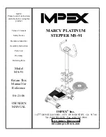
MARCY PLATINUM MS-91
Brand: MPEX Pages: 11

Perfect Binder G10 120
Brand: Riso Pages: 78

MicroFogger 3 Pro
Brand: Inventys Pages: 13

120-17B
Brand: Adler Pages: 5

Sfera 6-36 R/F
Brand: Necta Pages: 19

Minoltafax 1600e
Brand: Konica Minolta Pages: 127

Alto FLOORTEC 550 P
Brand: Nilfisk-Advance Pages: 60

56314019
Brand: Nilfisk-Advance Pages: 82

RP7010
Brand: Geemarc Pages: 19

Explorer 1500
Brand: Nobles Pages: 1

AMS-343B
Brand: JUKI Pages: 62

KISS PREMIUM
Brand: Stern Pinball Pages: 52
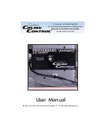
Quilter's Cruise Control Voyager 17
Brand: Hinterberg Design Pages: 3

DNU-1541-7
Brand: JUKI Pages: 50

HZL-E61
Brand: JUKI Pages: 72


