


Doc no. 2.100.011.1a
08/2018
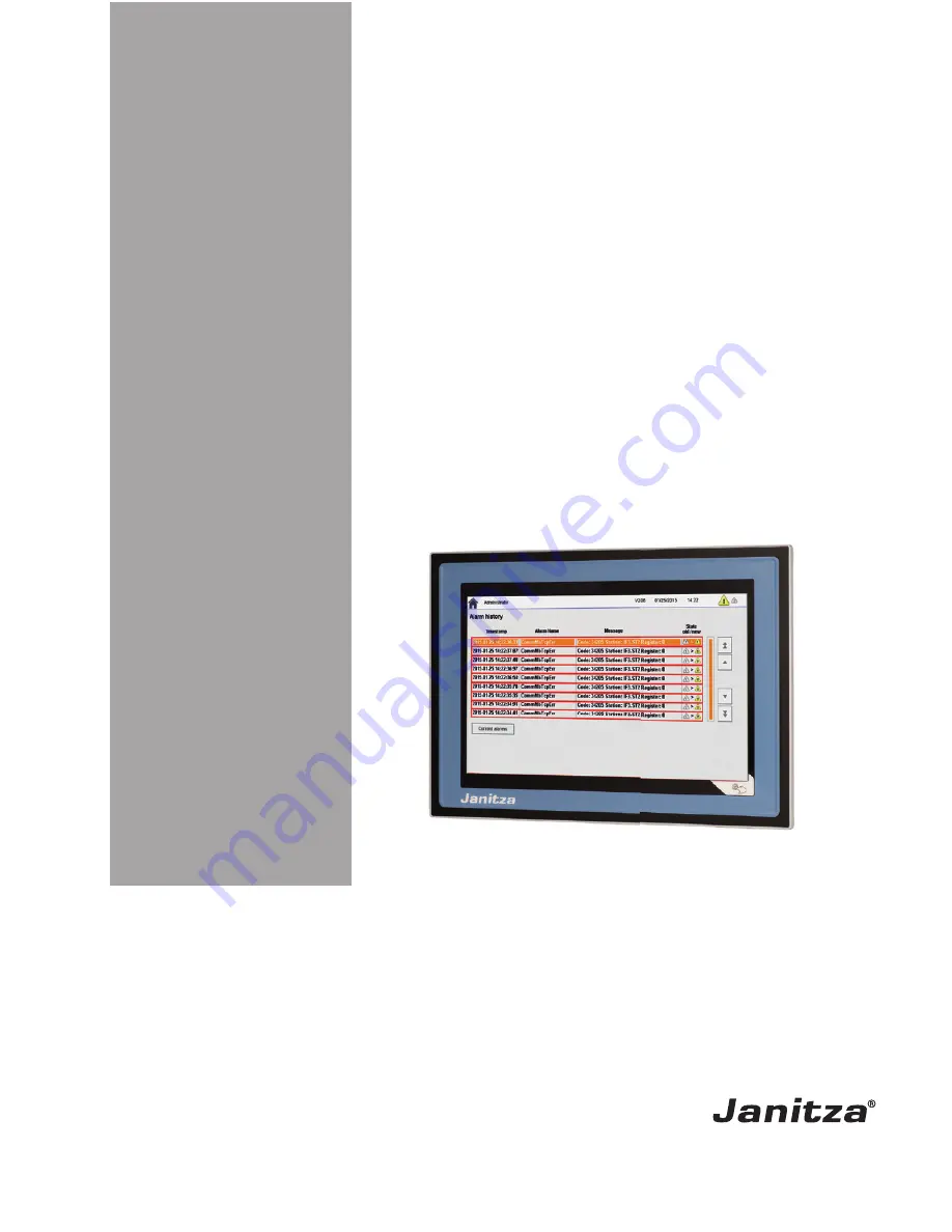
Smart Energy Panel
JPC70
User Manual and Technical Data
Janitza electronics GmbH
Vor dem Polstück 6
35633 Lahnau, Germany
Support tel. +49 6441 9642-22
Fax +49 6441 9642-30
Email: [email protected]
www.janitza.com
www
.janitza.com


