


JDN OPERATING AND ASSEMBLY INSTRUCTIONS
Hoist
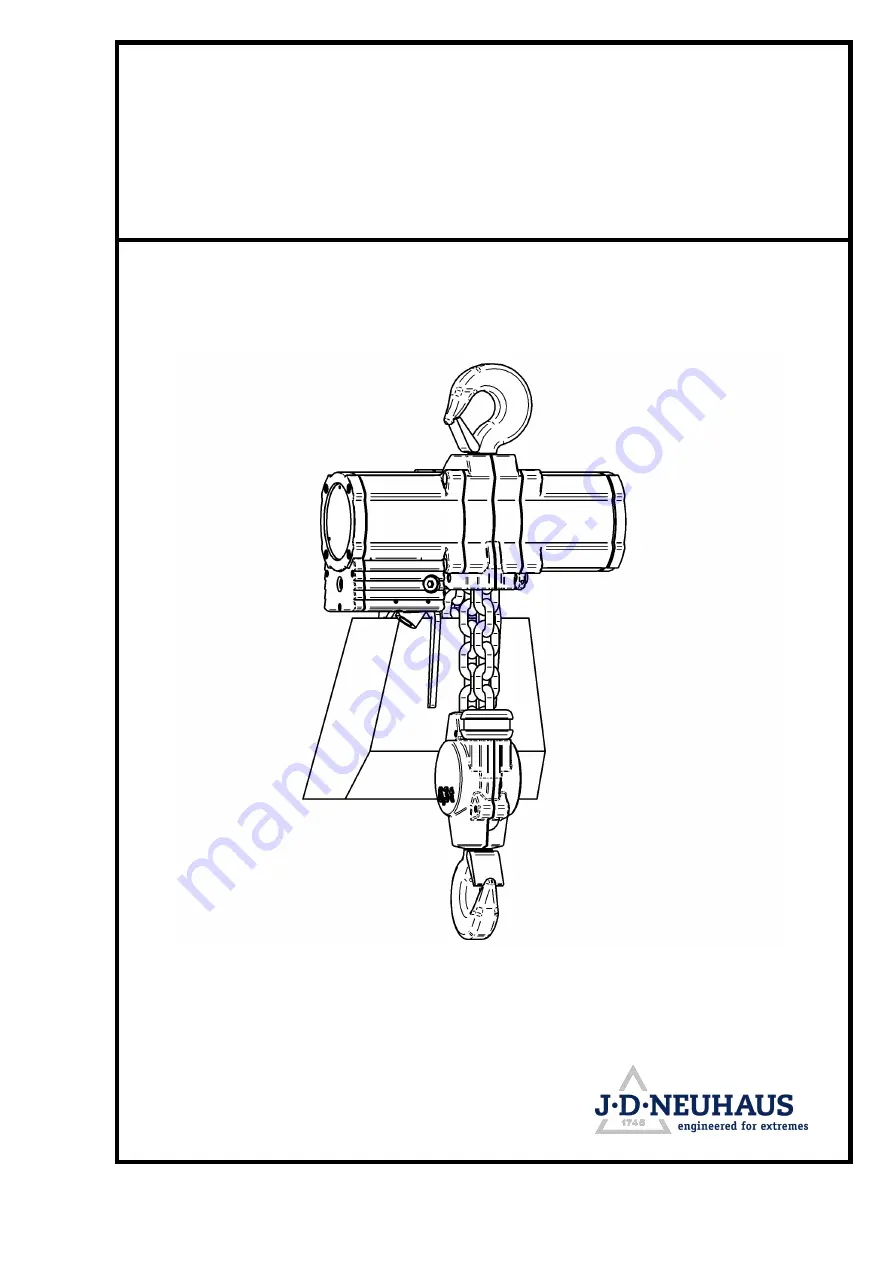
PROFI 6 TI
Serial No.: P706448
Doc.-No.: VA057988-10-OM-EN-0821-62-1
ORIGINAL OPERATING
AND ASSEMBLY INSTRUCTIONS
Representation may differ from actual product!
The J.D. NEUHAUS PROFI 6 Ti offers industry-leading quality and performance. Ensure a seamless experience with our comprehensive customer's operating and assembly instructions. Download the manual for free from our website, providing step-by-step guidance to maximize the potential of your J.D. NEUHAUS PROFI 6 Ti.
JDN OPERATING AND ASSEMBLY INSTRUCTIONS
Hoist
PROFI 6 TI
Serial No.: P706448
Doc.-No.: VA057988-10-OM-EN-0821-62-1
ORIGINAL OPERATING
AND ASSEMBLY INSTRUCTIONS
Representation may differ from actual product!


