


Intrepid Control Systems, Inc.
31601 Research Park Drive Madison Heights, MI 48071 USA
(ph) +1-586-731-7950 (fax) +1-586-731-2274
www.intrepidcs.com
www.aeta-rice.com
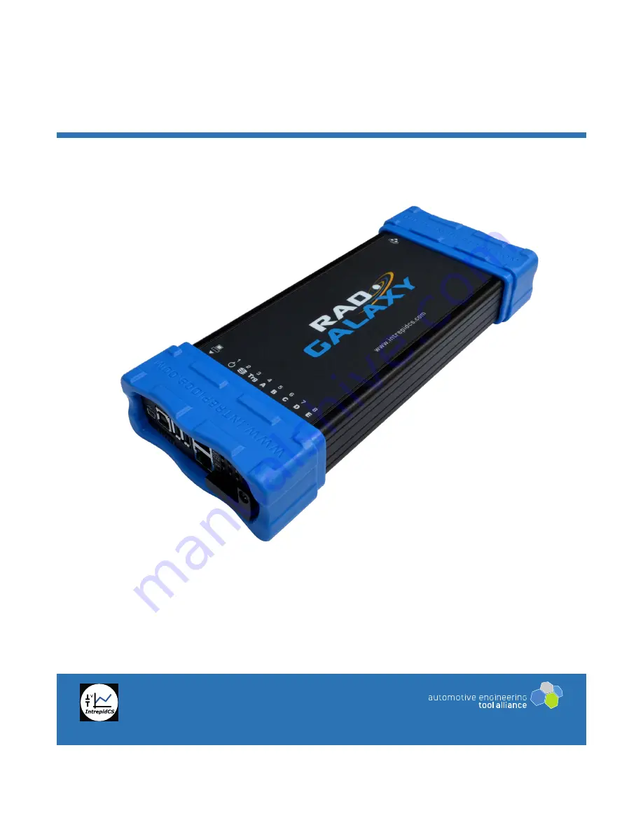
RAD-Galaxy
Multi Active Tap, Media Converter and
Network Interface for Automotive Ethernet and CAN FD
User’s Guide
Version 1.2 - November 28, 2017


