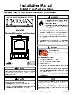
background image

PELLET STOVE  

OPERATING & INSTALLATION INSTRUCTIONS 


Inca Metal Cutting 
#100 – 11091 Bridgeport Road 
Richmond, B.C.  V6X 1T3 
Canada 

14142


Please read this entire manual before installation and use of this pellet fuel burning room 
heater.  Failure to follow these instructions could result in property damage, bodily injury or 
even death. 
Contact your local building officials about restrictions and installation inspection 
requirements in your area. 
Save these instructions. 

Tasman 40,000 
Free Standing 
Model   

Tasman 40,000 
Insert Model

Summary of Contents for Tasman 40000 free standing

Page 1: ...before installation and use of this pellet fuel burning room heater Failure to follow these instructions could result in property damage bodily injury or even death Contact your local building officials about restrictions and installation inspection requirements in your area Save these instructions Tasman 40 000 Free Standing Model Tasman 40 000 Insert Model ...

Page 2: ...s to Combustibles 14 15 Installing Your Room Heater 16 24 Mobile Home Installations 25 Insert Pellet Stove 26 28 Vent Termination Locations 29 Maintenance 30 33 Optional Accessories 34 Troubleshooting 35 41 Circuit Board Auger Timing 42 Wiring Diagram 43 Replacement Parts List 44 Warranty 45 47 Installation Information Sheet 48 Service Maintenance Log 49 ...

Page 3: ...ximum Premium grade 3 maximum Standard grade Moisture Content 8 maximum Heat Content minimum 8 200 btu hr It is important to note that the ash content of the fuel and frequency of operation determine the frequency of cleaning required for your unit A high ash fuel may result in your unit having to be cleaned daily while a low ash content fuel may permit a longer time between cleaning Occasionally ...

Page 4: ...outside combustion air source It is recommended that the exhaust vent be cleaned bi annually or after every two tons of pellets Soot or creosote may accumulate when the stove is operated under incorrect conditions such as an extremely rich burn black tipped lazy orange flames Do not operate the stove if the flame becomes dark or sooty or if the burn pot overfills with pellets Turn the stove off an...

Page 5: ...nts in your area Notify your insurance company of your new stove Allow the stove to cool before performing any maintenance Ashes must be disposed of in a metal container with a tight lid and placed on a non combustible surface well away from your home Check the venting system at least twice a year for creosote build up CAUTION DO NOT CONNECT TO ANY AIR DISTRIBUTION DUCT OR SYSTEM NEVER USE GASOLIN...

Page 6: ...CIFICATIONS Heating Specifications Burn Rate 40 000 btu hr or 4 8 lbs of fuel per hour Hopper Capacity 50 lbs Heating Efficiency 75 79 Depends on quality and heating value of pellet fuel DIMENSIONS Figure 1 ...

Page 7: ...7 DIMENSIONS The minimum installation dimensions of the insert opening are 22 558 80 mm wide x 22 3 4 578 mm high x 17 1 2 444 50 mm deep Figure 2 15 ...

Page 8: ...u can have full control of the pellet stoves control board functions and familiarize yourself with how the pellet stove works It is in this mode that the heat level for the T STAT mode is set To Start up a Cold Stove Press and release the On Off button The green light above the On Off button will flash to indicate that the start up cycle has started The light above the Auger button will turn on in...

Page 9: ...ximum at any heat setting they may do so by pressing the FAN button If the flame goes out use the AUGER TRIM button to make adjustments See the AUGER TRIM button description on page 11 To Shutdown Stove Turn off the unit by pressing the On Off button The stove will enter the shutdown cycle where the pellets will stop feeding to allow the fuel in the burn pot to be used up The exhaust blower and co...

Page 10: ...how the feed rate on level 1 At this point you can push the heat level button and set to desired feed rate setting 2 5 This only needs to be done once and then the stove will automatically cycle using the wall thermostat If the wall thermostat doesn t call for heat within 30 minutes the stove will go to full shut down mode and will shut itself off You do not need to touch the control board at this...

Page 11: ...burn pot when first using the pellet stove or when you completely empty the hopper of pellets and restarting after reloading the hopper You can load the auger faster by pressing and holding this button until you see pellets dropping into the burn pot This button will turn off after 1 minute and must be released and pressed again if you want to continue to manually operate the auger Auger Trim This...

Page 12: ...ull KEEP LID CLOSED AT ALL TIMES EXCEPT WHEN REFILLING DO NOT OVERFILL HOPPER Safety Features 1 Your unit is equipped with a high temperature limit thermo snap disc This snap disc serves to shutdown the auger in the case of an over temperature situation such as convection fan failure This disc has a manual reset button that will have to be reactivated once the unit has cooled down 2 If the combust...

Page 13: ...at Disconnect unit from power supply Open right side panel to gain access to rear of control panel Take the thermostat wires and connect to the green screw terminal on the rear of the control panel see Figure 4 When the room cools to below the thermostat setting the stove will automatically restart and run at the last feed rate setting When the room is warm enough the unit will shut off The exhaus...

Page 14: ... on a combustible floor a 1 2 thick non combustible hearth pad must be installed under the unit The pad must extend at least the width of the appliance and at least the depth of the appliance plus 6 152 mm in front of the appliance This applies for both the freestanding unit and the insert Alcove Dimensions Figure 5 Figure 6 ...

Page 15: ...d if its dimensions fall within the chart below Mantle Depth Mantle Height from Floor 10 254 mm 40 1016 mm 8 7 8 222 mm 39 991 mm 7 13 16 197 mm 38 965 mm 6 11 16 171 mm 37 940 mm 5 5 8 143 mm 36 914 mm 4 1 2 114 mm 35 889 mm 3 7 16 88 mm 34 864 mm 2 5 16 57 mm 33 838 mm 1 1 4 32 mm 32 813 mm Figure 7 ...

Page 16: ...chimney The chimney must be lined if over 6 150 mm in diameter or if it has a cross sectional area of over 28 square inches Venting can pass through the ceiling and roof if listed pipe is used Do not obtain combustion air from the attic garage or any other unventilated area You may obtain combustion air from a ventilated crawlspace DO NOT INSTALL A FLUE DAMPER IN THE EXHAUST VENTING SYSTEM OF THIS...

Page 17: ... air vent has a proper cap on it to prevent rodents from entering and also is installed where it won t become blocked with snow etc 8 Connect the exhaust vent pipe to the exhaust outlet of your appliance 9 Secure all vent joint connections with 3 screws Seal the exhaust vent joint connections with high temperature silicone sealant 10 Push the unit straight back to the interior wall but be sure to ...

Page 18: ...18 HORIZONTAL EXHAUST VENT INSTALLATION continued Figure 8 Figure 9 ...

Page 19: ...ot on your exterior wall and cut a hole 2 1 2 64 mm in diameter through the wall 5 Secure all vent joint connections with 3 screws Seal the exhaust vent joint connections with high temperature silicone sealant 6 Install the combustion air intake pipe 7 Install a tee with a cleanout on the exhaust pipe found at the rear of your unit 8 Install listed vent upward through the ceiling When you pass thr...

Page 20: ...d exhaust vent through the wall be sure to make sure that 3 75 mm clearances to combustibles are maintained 5 Secure all vent joint connections with 3 screws Seal the exhaust vent joint connections with high temperature silicone sealant 6 Install a Tee with a cleanout on the end of the exhaust pipe then install listed venting upward from there Be sure to install support brackets every 5 1500 mm to...

Page 21: ...21 SELKIRK DIRECT TEMP VENT SYSTEM FOR PELLET APPLIANCES Images courtesy of Selkirk ...

Page 22: ...22 SELKIRK DIRECT TEMP VENT SYSTEM FOR PELLET APPLIANCES Images courtesy of Selkirk UP OUT HORIZONTAL TERMINATION KIT Figure 12 ...

Page 23: ...23 SELKIRK DIRECT TEMP VENT SYSTEM FOR PELLET APPLIANCES Images courtesy of Selkirk STRAIGHT OUT HORIZONTAL TERMINATION KIT Figure 13 ...

Page 24: ...24 SELKIRK DIRECT TEMP VENT SYSTEM FOR PELLET APPLIANCES Images courtesy of Selkirk THROUGH THE ROOF VERTICAL TERMINATION KIT Figure 14 ...

Page 25: ...nsure that the unit is permanently electrically grounded to the chassis of your home IT IS MANDATORY TO TAKE THE COMBUSTION AIR FROM THE OUTSIDE WHEN INSTALLING THIS UNIT IN AIR TIGHT OR MANUFACTURED MOBILE HOMES CAUTION THE STRUCTURAL INTEGRITY OF THE MANUFACTURED HOME FLOOR WALL AND CEILING ROOF MUST BE MAINTIANED WARNING DO NOT INSTALL IN SLEEPING ROOM NOTE Only the freestanding model is for in...

Page 26: ...he shroud must be installed before unit is set into its final position Step 1 Shroud Side Facing the back of the unit take the left shroud side piece no control panel hole and fasten as shown with 2 screws provided Step 2 Shroud Side Facing the back of the unit take the right shroud side piece control panel hole and fasten as shown with 2 screws provided Figure 16 Figure 17 ...

Page 27: ...ke the top shroud side piece and fasten as shown with 4 screws provided Step 4 Control Board Take the control board and insert it from the back of the right shroud side facing front of unit Fasten control board in place with 4 screws provided top bottom of board Figure 18 Figure 19 ...

Page 28: ... air intake can be attached to the appliance by using a hose clamp 6 Connect the stove to the coupling on the bottom of the exhaust flex vent and twist to the locked position Push the appliance into the fireplace to its final position Go to the top of the chimney and pull the vent system up to the desired height 7 For the exhaust termination of the pellet vent use a tall cone flashing and a storm ...

Page 29: ...g F 12 30 cm To outside corner G 12 30 cm To inside corner combustible wall H 3 91 cm within a height of 15 4 5 m above the meter regulator assembly To each side of center line extended above natural gas or propane meter regulator assembly or mechanical vent I 3 91 cm From any forced air intake or other appliance J 12 30 cm Clearance to non mechanical air supply inlet to building or the combustion...

Page 30: ...pot regularly to check that the holes have not become plugged If necessary clean thoroughly It is imperative that the burn pot be re installed the correct way or the unit will not light The end of the burn pot with an igniter hole in it see Figure 22 must be installed facing the rear of the unit This hole allows the igniter to heat up the pellets to the point of ignition Figure 22 Igniter Hole Fig...

Page 31: ...or shop vac may have a special filter or bag available to eliminate this leakage 5 Remove ash pan and dispose of ashes into metal container 6 Reinstall ash pan 7 Reinstall burn pot and burn pot liner Ash Removal Insert Unit 1 Let the unit cool to room temperature then lift the ash pan door up and pull out 2 Follow directions for freestanding unit on previous page Ash Disposal Ashes should be place...

Page 32: ...EFORE SERVICING UNIT Over time ash or dust may accumulate on the blades of the convection combustion fans The fans should be inspected periodically and if any accumulation is present vacuumed clean as the ash or dust can impede the fans performance It is also possible that creosote may accumulate in the combustion fan this must be brushed clean The combustion fan can be found behind the left side ...

Page 33: ...ed To clean the chimney detach the vent where it attaches to the combustion blower If creosote has accumulated it should be removed Inspect the entire vent system from unit exhaust to termination Creosote should be removed with a brush specifically designed for the type of chimney in use It is recommended that a qualified service technician perform the inspection and required maintenance Glass Doo...

Page 34: ... an optional firebox decorative liner as well as a ceramic log set Decorative Liner Installation 1 Install the center panel be sure to line up the hole with the drop tube 2 Install the left and right panels Left Panel Right Panel All Panels Installed Figure 27 ...

Page 35: ...um in the firebox Check the vacuum switch by shorting out the vacuum switch then turn the control panel to OFF and back to ON If the unit starts to operate change the vacuum switch Check the exhaust temperature switch located on the exhaust blower by shorting out the exhaust temperature switch then turn the control panel to OFF and back to ON If the unit starts to operate change the exhaust temper...

Page 36: ...or if none check circuit board fuse Ensure the exhaust blower is operating Check the vacuum hose is connected or damaged Bypass the vacuum switch by placing a jumper wire on the two electrical connections If the auger motor starts to function normally replace the vacuum switch Check the manual reset on the 250 F high limit switch If the switch has been tripped check for the cause of the overheatin...

Page 37: ...intake may be dirty or partially blocked restricting airflow to the unit Burn pot holes are blocked Let the unit cool and clean burn pot and burn pot liner be sure to follow instructions for disposal of ashes found on page 31 Circuit board malfunction Time the fuel feed light at each setting after the stove has completed the initial Start Up sequence Check the timing against the timing chart found...

Page 38: ...ect power then change out the fan Stove times out on start up cycle goes to shut down Stove is not getting to temperature in time and therefore goes to automatic shut down everything will turn off including the convection fan If it is an old board 12 minute cycle start again and wiggle low limit switch If you have to wiggle switch more than once then change low limit switch If problem persists the...

Page 39: ...or more than 1 minute 1 minute until vacuum failure 10 minute shut down cycle then replace the vacuum switch Stove shuts down flashes level 3 This indicates that the stove was starved for fuel Check that the auger is functioning properly and that there is fuel in the pot and hopper Make sure there are no jams If the fuel is being feed properly then restart the stove by holding down the start butto...

Page 40: ...in the house then you will want to check that your exhaust is hooked up properly to code and that it is COMPLETELY SEALED this is very important this is the main cause of most smoke issues Check to make sure your intake is going to the outside and is sealed properly If problem persists then get a new board with the extended shut down cycle on it and the exhaust fan will stay on for 10 minutes afte...

Page 41: ...he main issue with most pellet jams If there is no pellet jam then check the high limit switch if it is tripped it will stop the pellets from feeding as well Burn pot is clogging up You must clean pot regularly how regularly depends on usage Failure to clean out the burn pot will cause build up and clogging It could also lead to a hopper fire should the pot clog up and back up the drop tube IT IS ...

Page 42: ...5 LEVEL 3 4 4 LEVEL 4 4 5 3 5 LEVEL 5 5 5 2 5 MODE B SHOULD SHIP IN THIS MODE 8 SECOND CYCLE SETTING TIME ON TIME OFF START UP 2 5 5 5 PIN POSITION LEVEL 1 2 6 LEVEL 2 2 5 5 5 LEVEL 3 3 5 4 5 LEVEL 4 4 4 LEVEL 5 5 3 MODE C 8 SECOND CYCLE SETTING TIME ON TIME OFF START UP 2 5 5 5 PIN POSITION LEVEL 1 2 6 LEVEL 2 2 5 5 5 LEVEL 3 3 5 LEVEL 4 3 5 4 5 LEVEL 5 4 4 ...

Page 43: ...43 WIRING DIAGRAM ...

Page 44: ...art control panel circuit board SPSS 1007 auger motor SPSS 1005 250 F normally open high limit snap disc SPSA 1016 140 F normally open exhaust temperature snap disc SPSA 1015 convection fan SPSS 1002 exhaust fan SPSS 1000 0 1 w c normally open vacuum switch SPSA 1010 silicone tube for vacuum switch SPSA 1011 hot rod ignitor SPSA 1012 door gasket door glass front panel SPSS 1017 door glass side pan...

Page 45: ...ontransferable and is made only to the original purchaser The warranty shall commence no later than 24 months following the date of product shipment from Inca Metal regardless of the installation or occupancy date It is strongly recommended that this appliance be installed by a licensed and qualified installer It must be installed operated and maintained at all times in accordance with the instruc...

Page 46: ...ll warranty claims then send a copy of the Warranty Claim Form to the manufacturer for review keep original form w part If this sheet is not filled out correctly and entirely when returned to Inca then a claim may be denied DO NOT SEND ANY PARTS BACK TO THE MANUFACTURER WITHOUT RMA Any claims under this warranty must be made by the dealer to the distributor If an inspection by the distributor indi...

Page 47: ...d including but not limited to environmental conditions such as rooftops buildings nearby trees hills mountains inadequate vents excessive venting configurations insufficient make up air or negative air pressures which may or may not be caused by mechanical systems such as exhaust fans furnaces clothes dryers etc Inca metal does not accept responsibility legal or otherwise for incidental or conseq...

Page 48: ...lled for warranty purposes and future reference Failure to properly fill out this sheet will void all future warranties NAME OF OWNER NAME OF DEALER ADDRESS ADDRESS PHONE PHONE MODEL NAME NAME OF INSTALLER SERIAL SIGNATURE DATE OF PURCHASE DATE OF INSTALLATION MANUFACTURED BY INCA METAL PRODUCTS LTD RICHMOND BC ...

Page 49: ...49 SERVICE AND MAINTENANCE LOG SERIAL OF STOVE _______________ DATE SERVICED PERFORMED BY DESCRIPTION OF SERVICE 12 2009 ...

Reviews: