background image

Interflex Datensysteme GmbH   

1/13 


Thank you for choosing a product from Interflex. With this product, you have purchased a reliable device for 

access control. 


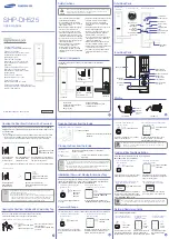
1.1  Scope of delivery 


  IF-80x Outdoor terminal (slave) 

  I/O controller board for controlling locking devices 

  Material for fastening 

  8-pin terminal strip 

  Blue wire for grounding the back panel 

  Mortise lock 

  Plastic strips for sealing the mortise lock 

  Adhesive tape for mounting the I/O controller board 


  Please check the completeness and condition of the 

shipment upon receipt. 


1.2  CE conformity 

  The device complies with the requirements of the respective EU guidelines (CE conformity). 

Modifications to the device are not permitted.


All information contained in this documentation is accurate at the time of printing. All specifications are 

subject to change without notice. 
The product brand names and trademarks specified in this documentation are protected by commercial and 

patent laws. 


1.3  Shielded cables 

To ensure malfunction-free operation, we recommend the use of shielded bus cables. 
Operation is also possible with unshielded cables. In case of transmission problems, you will have to 

examine the reasons in each individual case. Where necessary, a shielded cable should be used for the 

connection of the respective devices. 


1.4  Intended use 

The device is used for reading RFID credentials, e.g. in access control systems, and also for controlling 

locking devices. Any other use is not in accordance with the intended purpose and is therefore not permitted. 


1.5  Function 

Slave terminals of series IF-80x Outdoor are used for: 

  controlling the access of people who identify themselves via an RFID credential before entering a 

security zone. 

  controlling and monitoring locking devices that prevent uncontrolled (physical) access to security zones. 

  writing NetworkOnCard access rights. The data is used for identification at offline devices, e.g. electronic 

door fittings. 

95-10330 V2017-07-24 

IF-80x Outdoor Slave Terminal 

Summary of Contents for IF-80x

Page 1: ...ocumentation are protected by commercial and patent laws 1 3 Shielded cables To ensure malfunction free operation we recommend the use of shielded bus cables Operation is also possible with unshielded...

Page 2: ...ices They are generally connected to a master terminal access manager or terminal controller via an RS485 data cable These terminals are designed for controlling the access of persons who identify the...

Page 3: ...appliance case 2 Alternative mounting hole for wall mounted cable inserted from the bottom 6 Mounting holes for US standard 3 Cable gland 7 Hole for adjusting the reader 4 Horizontal mounting option...

Page 4: ...ce Use only the original screws and do not use any washers Screws placed too high can cause collisions with other components and damage the device Ensure short cable routing Cable loops can damage the...

Page 5: ...ire is wrapped around the insulation 8 The blue wire and the PE wire from the I O controller board are connected to terminal 8 on the terminal strip 7 The blue wire is connected to the strain relief 9...

Page 6: ...rminal 3 Patch cable from computer to switch or hub 6 RS 485 data cable from controller master terminal to I O controller board Please refer to the table Function of Cables and Cable Types for detaile...

Page 7: ...e wire under a nut of the strain relief 12 Now connect all of the cables coming from the I O controller board to the terminal strip of the terminal Then connect the blue wire from the back panel of th...

Page 8: ...cuit example Power supply 7 Address switch on the I O controller board 4 Circuit example RS485 connection The spur line may not be longer than max 100 m Bridges Br 1 When one I O controller board is u...

Page 9: ...door terminal is usually very long we recommend connecting the power supply and the relay contact with one cable pair each 4 5 Connecting a further I O controller board If more than two inputs or more...

Page 10: ...maximum Setting the LEDs Use the DIP switch 4 to set the LEDs according to the color of the display The switch setting is usually preset factory default Check the setting of the DIP switches accordin...

Page 11: ...the terminal number Example cfg address 8 has been set Enter this command etp address cx The controller responds with TC ET 8 Then the command 34xxyy is sent directly to the terminal Example Address...

Page 12: ...board Br 2 Bridge 2 is used to set the switching contacts of the NO NC relay Br 3 Instead of bridge 3 an anti tamper switch can be connected See also Wiring Overview 8 7 Initial Operation Once you hav...

Page 13: ...condensing Protection category III Degree of protection IP54 provided that the cables are installed according to instructions The lower cable inlet must be masked using the included adhesive strip Dim...

Reviews: