background image


INSTALLATION, SERVICE AND 

MAINTENANCE INSTRUCTIONS 
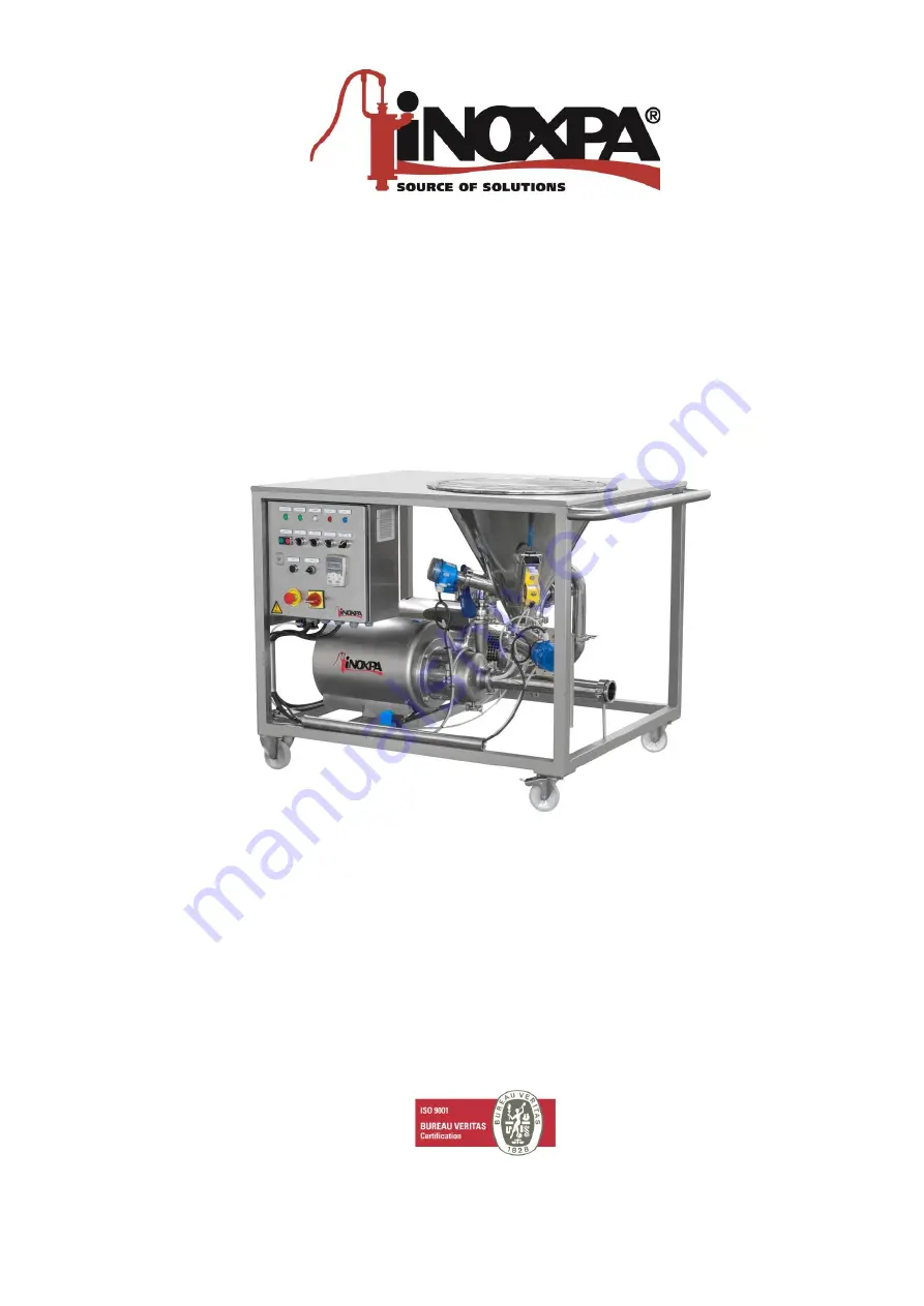
 

Table blender 

MM-1, MM-2, MM-3 


INOXPA, S.A.  

c/Telers, 54 Aptdo. 174 

E-17820 Banyoles 

Girona (Spain) 

Tel. : (34) 972 - 57 52 00 

Fax. : (34) 972 - 57 55 02 

email: [email protected] 

www.inoxpa.com


Original Manual 

02.100.30.01EN 

2021/11

(A) 

Summary of Contents for MM

Page 1: ...ENANCE INSTRUCTIONS Table blender MM 1 MM 2 MM 3 INOXPA S A c Telers 54 Aptdo 174 E 17820 Banyoles Girona Spain Tel 34 972 57 52 00 Fax 34 972 57 55 02 email inoxpa inoxpa com www inoxpa com Original Manual 02 100 30 01EN 2021 11 A ...

Page 2: ......

Page 3: ......

Page 4: ...a safe location near the installation area 1 3 SAFETY 1 3 1 Warning symbols Safety hazard for people in general Danger of injury caused by rotating equipment parts Electric hazard Danger Caustic or corrosive agents Danger Suspended loads Danger for the correct operation of the equipment Mandatory to ensure safety at the workplace Mandatory use of safety goggles 1 4 GENERAL SAFETY INSTRUCTIONS Read...

Page 5: ...ust be carried out by authorised personnel 1 4 4 Compliance with the instructions Not following the instructions may impose a risk for the operators the environment and the machine and may result in the loss of the right to claim damages This non compliance may result in the following risks Failure of important machine plant functions Failure of specific maintenance and repair procedures Possible ...

Page 6: ...parts and accessories The usage of other parts will relieve the manufacturer of any liability Changing the service conditions can only be carried out with prior written authorisation from INOXPA Please do not hesitate to contact us in case of doubts or if further explanations are required regarding specific data adjustments assembly disassembly etc ...

Page 7: ...pes 10 4 5 Double mechanical seal 11 4 6 Electrical installation 11 5 Starting the blender 5 1 Start up 13 6 Operating problems 7 Maintenance 7 1 General considerations 15 7 2 Storage 15 7 3 Cleaning 15 7 4 DisAssembly Assembly of the table blender 17 8 Technical Specifications 8 1 Technical Specifications 19 8 2 Tightening torques 20 8 3 Weights 20 8 4 Table blender dimensions MM 1 MM 2 MM 3 21 8...

Page 8: ... is normally created by the equipment feed backpressure being too high the flow may not be able to sweep the solids that are being added or even the liquid may not be able flow up the pipe and into the hopper Improper pressure The differential pressure of the blender must be low 6 9 m the same as the pressure at the inlet to the blender which must be negative but without resulting in cavitation si...

Page 9: ...pump products with a high viscosity The maximum viscosity of the blenders is 400 cps Incompatible products Products incompatible with the different mechanical seals and elastomers 3 4 APPLICATION These blenders can be used in any process where first powder is added and then it is dissolved in a liquid Examples Powdered milk Powdered serum Milkshakes Sauces Brines Fertilizers Lactose Syrups Stabili...

Page 10: ... Unpack the blender and check the following The suction and discharge connections and the hopper of the blender removing any remaining packaging material Check that the pump and mixer if there is have not suffered any damage If not in good material condition and or if not all the parts are included the shipping carrier should submit a report as soon as possible 4 1 1 Identification of the blender ...

Page 11: ...lines in straight sections with the minimum possible number of elbows and fittings in order to reduce any pressure losses that may be caused by friction Make sure that the blender s ports are properly aligned with the pipework and have a diameter similar to that of the pump connections Place the blender as close as possible to the suction tank and whenever possible below the liquid level or even b...

Page 12: ...connections Electrical equipment terminals and components of the control systems may still carry current when they are disconnected Contacting them may impose a hazard to operators or cause irreparable material damage Prior to handling the blender make sure that the electrical panel is disconnected Connect the motor in accordance with the instructions supplied by the motor manufacturer Check the d...

Page 13: ... that the motor fan rotates in a clockwise direction ALWAYS check the direction of rotation of the motor with liquid inside the blender For models with a seal chamber ALWAYS ensure that it is full of liquid prior to checking the direction of rotation 02 100 32 0006 ATTENTION See indicator label on the pump and or the mixer ...

Page 14: ...otation of the motor is correct If the blender has double mechanical seal check that the cooling circuit are connected 5 1 2 Checks when starting the table blender Check that the blender is not making any strange noises Check if the absolute inlet pressure is sufficient to prevent cavitation in the blender Check the curve to obtain the minimum required pressure above the vapour pressure NPSHr Cont...

Page 15: ...sure Discharge pressure too high If necessary reduce the pressure losses for example by increasing the pipe diameter Flow rate too high Reduce the flow by means of a diaphragm Partially close the discharge valve Trim the impeller Decrease speed Viscosity of the liquid too high Reduce the viscosity for example by heating the liquid Liquid temperature is too high Decrease the temperature by cooling ...

Page 16: ...pump or mixer 7 2 STORAGE Before storing the blender it should be completely drained Prevent as far as possible exposing the parts to excessively humid environments 7 3 CLEANING The use of aggressive cleaning products such as caustic soda and nitric acid may burn the skin Use rubber gloves during the cleaning process Always use protective goggles 7 3 1 CIP Clean in Place cleaning If the blender is...

Page 17: ...m sterilization process The parts materials will not be damaged if the indications specified in this manual are observed Make sure that no cold liquid enters the system until the temperature of the blender is lower than 60 C 140 F The blender generates an important pressure loss through the sterilization process We recommend the use of a branch circuit with a discharge valve to ensure that steam s...

Page 18: ...ttached 3 Remove the butterfly valve 96 removing the clamp 91 and the seal 91C below it 4 Open the tube clamp 38A to loosen the venturi tube 102 Then remove the clamp 91 and seal 91B that fasten the venturi tube 102 to the pumpcasing 5 Remove discharge tube 98 that connects the pump 01 to the elbow clamp 91F from the mixer entrance 02 by removing clamp 91D and seal 91E from the outlet pump and the...

Page 19: ...02 by means of seal 91B and clamp 91 6 To assembly the hopper put the flat washer 18 on the frame 38 by aligning the seal drill holes with those on the frame 7 Place the hopper 101 on the frame 38 aligning the threaded studs used for fixing the hopper 101 with the drill holes on the frame 38 and the seal 18 8 Join the hopper to the butterfly valve 96 by means of seal 91B and clamp 91 9 Fasten the ...

Page 20: ...gle or double seal balanced Material of rotating part Silicon carbide SiC standard Material stationary part Silicon carbide SiC standard Gasket material EPDM standard Water consumption double seal 0 25 to 0 6 l min Pressure double seal from atmospheric to 100 kPa 1 bar When the sound pressure level in the operating area exceeds 80 dB A appropriate personal protective equipment must be used SIZE Ce...

Page 21: ...otherwise the torques listed in the following table should be applied on the nuts and bolts of this blender Size Nm lbf ft M6 10 7 M8 21 16 M10 42 31 M12 74 55 M16 112 83 8 3 WEIGHTS Size kg lbs MM 1 130 287 MM 2 185 408 MM 3 355 783 MM 1M 220 485 MM 2M 305 673 MM 3M 630 1390 ...

Page 22: ...0 1000 352 MM 2 2 2 194 660 802 337 800 1345 1017 MM 3 4 3 240 801 1055 422 950 1780 1228 455 8 5 TABLE BLENDER DIMENSIONS MM 1M MM 2M MM 3M SIZE DNa DNi A B C D E F G H J MM 1M 2 2 133 564 701 320 1000 1190 1000 352 387 MM 2M 2 2 137 588 849 337 1080 1345 1017 407 MM 3M 4 3 176 725 1089 422 1330 1780 1228 455 479 02 100 32 0009 02 100 32 0010 ...

Page 23: ...gonal screw 4 A2 53 Flat washer 24 A2 53A Flat washer 4 A2 54 Blind nut 8 A2 76 Fixed wheel 2 Nylon 76A Rotating wheel 2 Nylon 91 Clamp 3 AISI 304L 91A Clamp 1 AISI 304L 91B Clamp seal 3 EPDM 91C Clamp seal 1 EPDM 91F 90º elbow clamp 1 AISI 316L 91G Clamp 1 AISI 304L 91H Blind clamp ferrule 1 AISI 316L 91I Clamp seal 3 EPDM 96 Butterfly valve 1 AISI 316L 97 Electrical panel 1 AISI 304L 101 Hopper ...

Page 24: ...A2 53A Flat washer 8 A2 54 Blind nut 8 A2 76 Fixed wheel 2 Nylon 76A Rotating wheel 2 Nylon 91 Clamp 3 AISI 304L 91A Clamp 3 AISI 304L 91B Clamp seal 3 EPDM 91C Clamp seal 3 EPDM 91D Clamp 2 AISI 304L 91E Clamp seal 2 EPDM 91F 90º elbow clamp 2 AISI 316L 91G Clamp 1 AISI 304L 91H Blind clamp ferrule 1 AISI 316L 91I Clamp seal 3 EPDM 96 Butterfly valve 1 AISI 316L 96A Discharge pump valve 1 AISI 31...

Page 25: ......

Page 26: ......

Page 27: ......

Page 28: ... 8882 e mail colombia inoxpa com e mail inoxpa au inoxpa com INOXPA ALGERIE INOXPA SOUTH AFRICA PTY LTD INOXPA USA Inc ROUIBA JOHANNESBURG SANTA ROSA Tel 213 21856363 21851780 Tel 27 117 945 223 Tel 1 7075 853 900 Fax 213 21854431 Fax 27 866 807 756 Fax 1 7075 853 908 e mail inoxpalgerie inoxpa com e mail sales inoxpa com e mail inoxpa us inoxpa com INOXPA UK LTD S T A PORTUGUESA LDA INOXPA ITALIA...

Reviews: