background image

Refer All Communications to the Nearest
Ingersoll–Rand Office or Distributor.

 Ingersoll–Rand Company 1999

Printed in U.S.A.

03539418

Form P7071
Edition 5
March, 1999

OPERATION AND MAINTENANCE MANUAL

for

MODELS 2934P2 AND 2940P2 SUPER DUTY IMPACTOOLS

Models 2934P2 and 2940P2 Impactools are designed for use in structural fabrication, machinery
maintenance, railroad maintenance, pipe and valve flange applications and installation of lag
screws.
Ingersoll–Rand is not responsible for customer modification of tools for applications on which
Ingersoll–Rand was not consulted.

IMPORTANT SAFETY INFORMATION ENCLOSED.

READ THIS MANUAL BEFORE OPERATING TOOL.

IT IS THE RESPONSIBILITY OF THE EMPLOYER TO PLACE THE INFORMATION

IN THIS MANUAL INTO THE HANDS OF THE OPERATOR.

FAILURE TO OBSERVE THE FOLLOWING WARNINGS COULD RESULT IN INJURY.

PLACING TOOL IN SERVICE

Always operate, inspect and maintain this tool in
accordance withAmerican National Standards
Institute Safety Code for Portable Air Tools
(ANSI B186.1).

For safety, top performance, and maximum durability
of parts, operate this tool at 90 psig (6.2 bar/620 kPa)
maximum air pressure at the inlet with 3/4” (19 mm)
inside diameter air supply hose.

Always turn off the air supply and disconnect the air
supply hose before installing, removing or adjusting
any accessory on this tool, or before performing any
maintenance on this tool.

Do not use damaged, frayed or deteriorated air hoses
and fittings.

Be sure all hoses and fittings are the correct size and
are tightly secured. See Dwg. TPD905–1 for a typical
piping arrangement.

Always use clean, dry air at 90 psig (6.2 bar/620 kPa)
maximum air pressure.  Dust, corrosive fumes and/or
excessive moisture can ruin the motor of an air tool.

Do not lubricate tools with flammable or volatile
liquids such as kerosene, diesel or jet fuel.

Do not remove any labels. Replace any damaged label.

USING THE TOOL

Always wear eye protection when operating or
performing maintenance on this tool.

Always wear hearing protection when operating this
tool.

Keep hands, loose clothing and long hair away from
rotating end of tool.

Note the position of the reversing lever before
operating the tool so as to be aware of the direction of
rotation when operating the throttle.

Anticipate and be alert for sudden changes in motion
during start up and operation of any power tool.

Keep body stance balanced and firm.  Do not
overreach when operating this tool.  High reaction
torques can occur at or below the recommended air
pressure.

Tool shaft may continue to rotate briefly after throttle
is released.

Air powered tools can vibrate in use.  Vibration,
repetitive motions or uncomfortable positions may be
harmful to your hands and arms.  Stop using any tool
if discomfort, tingling feeling or pain occurs.  Seek
medical advice before resuming use.

Use accessories recommended by Ingersoll–Rand.

Use only impact sockets and accessories.  Do not use
hand (chrome) sockets or accessories.

Impact wrenches are not torque wrenches.
Connections requiring specific torque must be
checked with a torque meter after fitting with an
impact wrench.

This tool is not designed for working in explosive
atmospheres.

This tool is not insulated against electric shock.

The use of other than genuine Ingersoll–Rand replacement parts may result in safety hazards, decreased tool performance, and
increased maintenance, and may invalidate all warranties.
Repairs should be made only by authorized trained personnel.  Consult your nearest Ingersoll–Rand Authorized Servicenter.

  F

E

P

TPD1362

Summary of Contents for 2934P2

Page 1: ...fumes and or excessive moisture can ruin the motor of an air tool Do not lubricate tools with flammable or volatile liquids such as kerosene diesel or jet fuel Do not remove any labels Replace any da...

Page 2: ...teners with specific torque requirements must be checked with suitable torque measuring devices after installation with an impact wrench Models 2934P2 2940P2 Impactools are equipped with a combination...

Page 3: ...Gun into the Grease Fitting For Model 2940P2 Before starting the tool and after each two or three hours of operation unless the air line lubricator is used detach the air hose an inject about 3 cc of...

Page 4: ...bles ou volatiles tels que le k ros ne le gasol ou le carburant d aviation Ne retirer aucune tiquette Remplacer toute tiquette endommag e UTILISATION DE L OUTIL Porter toujours des lunettes de protect...

Page 5: ...chocs ne sont pas des appareils dynamom triques Les fixations n cessitant un couple de serrage sp cifique doivent tre v rifi es avec des appareils de mesure de couple appropri s apr s avoir t assembl...

Page 6: ...e 2940P2 Avant de mettre l outil en marche et toutes les deux ou trois heures de fonctionnement si un lubrificateur de ligne n est pas utilis d brancher le flexible d alimentation et verser environ 3...

Page 7: ...tropear el motor de una herramienta neum tica No lubrique las herramientas con l quidos inflamables o vol tiles tales como queroseno gasoil o combustible para motores a reacci n No saque ninguna etiqu...

Page 8: ...AVISO Las llaves de impacto no son llaves de par Las fijaciones de espec fico requerimiento de par deber n ser comprobadas con un torsi metro adecuado despu s de su fijaci n con una llave de impacto L...

Page 9: ...a Modelo 2940P2 Antes de poner la herramienta en marcha y despu s de cada dos o tres horas de uso a menos que se haya puesto lubricante de l nea de aire comprimido desconecte la manguera de aire e iny...

Page 10: ...N o lubrifique as ferramentas com l quidos inflam veis ou vol teis tais como querosene diesel ou combust vel de jactos N o remova nenhum r tulo Reponha qualquer r tulo danificado USANDO A FERRAMENTA U...

Page 11: ...S AJUSTANDO O REGULADOR DE POT NCIA ADVERT NCIA As Ferramentas pneum ticas de impacto n o s o aparelhos de controlo de bin rio Apertos com requisitos de torque espec ficos devem ser verificados com ap...

Page 12: ...rifica o No R000A2 228 no Adaptador Para o Model 2940P2 Antes de operar a Ferramenta e depois de oito horas de opera o ao menos que esteja usando um lubrificador de ar de linha injecte aproximadamente...

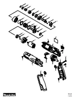
Page 13: ...MAINTENANCE SECTION 13 Dwg TPA1337 1...

Page 14: ...ve Stem 12 Exhaust Deflector Seal 2934P 789 O Ring 293 669 13 Reverse Valve Bushing 2934P 330S 2940P 330S 28 Trigger Retaining Pin AF120 322 14 Air Port Gasket 2 R44H 210A R44H 210A 29 Reverse Valve A...

Page 15: ...Lock 56 Rotor 2934 53 2940 53 Washer 4 8U 58 10 AV1 255 57 Vane Packet Set of 6 Vanes 2934 42 6 2940 42 6 43 Housing Cover Capscrew 4 510 638 510 638 58 Front End Plate 2934 11 2934 11 44 Housing Cove...

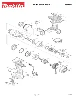
Page 16: ...MAINTENANCE SECTION 16 SPLINE DRIVE ANVIL Dwg TPA1338...

Page 17: ...01 69 Hammer Case Assembly for 2934P EU 2934P EU 301 for 2934P 2934 A727 for 2940P 2940P 301 for 2934P EU 2934P EU A727 for 2940P EU 2940P EU 301 for 2940P 2940 A727 Nameplate Screws 3 C32 302 for 294...

Page 18: ...mer Case Bushing 47 Inject approximately 6 cc of grease into the Grease Fitting 2 Fill the oil reservoir in the handle with Ingersoll Rand No 50 Oil Inject approximately 3 cc of oil into the air inlet...

Page 19: ...is removed abruptly 4 With the Impactool turned toward you and the Trigger 16 secured by an alternate means use a Pin Punch to drive out the Trigger Retaining Pin 18 5 Remove Trigger Bushing 19 For Mo...

Page 20: ...s the bearing into the Rear End Plate 55 6 Using a sleeve that will contact only the inner ring of the Rear Rotor Bearing press the assembled bearing and end plate onto the short hub of the Rotor 7 Be...

Page 21: ...ne side When properly installed in the Hammer Frame these undercuts must face each other 3 Replace Hammer Pins 66 4 Examine the base of the Anvil 68 or 69 and note its contour While looking down throu...

Page 22: ...and clean all parts with a clean suitable cleaning solution in a well ventilated area Reassemble tool as instructed in this manual Improper positioning of Reverse Valve Make certain the Reverse Valve...

Page 23: ...23 NOTES...

Reviews: