ImproX XDT900-0-0-GB-XX, Руководство по установке
"Устройство ImproX XDT900-0-0-GB-XX - это высококачественное оборудование, которое обеспечит надежную защиту вашего дома или бизнеса. Для правильной установки и использования необходимо ознакомиться с Руководством по установке, которое можно скачать бесплатно с нашего сайта. Посетите manualshive.com прямо сейчас!"
Поделиться
Скачать


Отзывы:
Нет отзывов
Похожие инструкции для XDT900-0-0-GB-XX
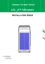
XCL AT-150 SERIES
Бренд: XAC Страницы: 8

EZPOS70-2B-C1G
Бренд: EBN Technology Страницы: 21

POS MobilePro
Бренд: Vectron Страницы: 112

WT-1018
Бренд: Witura Страницы: 10

RealPOS 5977
Бренд: NCR Страницы: 172

ABOX-110 Series
Бренд: AdvanPOS Страницы: 43

TC-1511-IP
Бренд: CommScope Страницы: 9

H-13
Бренд: Opticon Страницы: 4

Ingenico IPP320 PEDPack
Бренд: Tailwind Страницы: 2

MORPHOACCESS 200
Бренд: Sagem Страницы: 118

FastLane SelfServ 7358-K112
Бренд: NCR Страницы: 39

AerPOS AP-3617
Бренд: FEC Страницы: 49

PDK USB3-CBG06S
Бренд: IEE Страницы: 10

SP-1030
Бренд: Partner Страницы: 80

REL 551 2.5
Бренд: ABB Страницы: 88

HDT 600
Бренд: Motorola Страницы: 28

2436DW
Бренд: Wang Страницы: 90

2711-B6C series
Бренд: Allen-Bradley Страницы: 64


